
Method and system for adjusting parameters of signal receiving circuit of downhole repeater

A signal receiving and repeater technology, applied in transmission systems, electrical components, etc., can solve the problems of inability to use adaptive filtering technology, high complexity, large circuit size, etc. Less resources and smaller hardware circuit size

Active Publication Date: 2016-11-23
CHINA PETROLEUM & CHEM CORP +1
View PDF7 Cites 5 Cited by
  • Summary
  • Abstract
  • Description
  • Claims
  • Application Information

AI Technical Summary

Problems solved by technology

[0006] Secondly, at present, there are generally two methods to realize filters with adjustable passbands. One is to use a combination of multiple analog filter circuits with different passbands, and select the circuit with the corresponding passband according to different carrier frequencies to switch. Large size and high power consumption. The repeater is powered by a lithium battery, which has strict requirements on circuit power consumption, and the underground space is limited, so this method cannot be used
The second is to use adaptive digital filtering technology and use software to adjust the passband of the filter, but this kind of software is complex and will take up a lot of resources and processing time
However, the performance of the high-temperature CPU chip used in the repeater is limited (at present, embedded chips such as single-chip microcomputer, FPGA, and DSP can meet the high temperature requirement of 125°C, and the maximum main frequency is only a few hundred M, which is far lower than that of a PC). , demodulation, decoding, signal processing, modulation, encoding, transmission and a series of work, leaving only 90ms for the processing time of each electromagnetic signal received, it is impossible to use adaptive filtering technology

Method used


Image

  • Method and system for adjusting parameters of signal receiving circuit of downhole repeater
  • Method and system for adjusting parameters of signal receiving circuit of downhole repeater
  • Method and system for adjusting parameters of signal receiving circuit of downhole repeater

Examples


Embodiment Construction

[0046] The implementation of the present invention will be described in detail below in conjunction with the accompanying drawings and examples, so as to fully understand and implement the process of how to apply technical means to solve technical problems and achieve technical effects in the present invention. It should be noted that, as long as there is no conflict, each embodiment and each feature in each embodiment of the present invention can be combined with each other, and the formed technical solutions are all within the protection scope of the present invention.

[0047] figure 1 A structural block diagram of the signal receiving circuit of the downhole repeater is shown. Such as figure 1 As shown, the signal receiving circuit of the downhole repeater mainly includes a gain amplifier circuit 3, an analog filter circuit 28 and a digital filter (not shown in the drawings). Wherein, the gain amplification circuit 3 and the analog filter circuit 28 are realized by the a...


PUM


Abstract

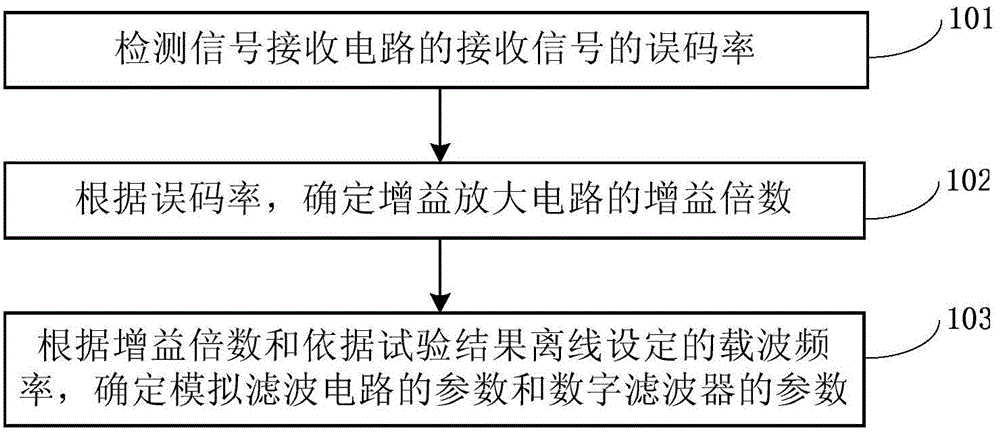
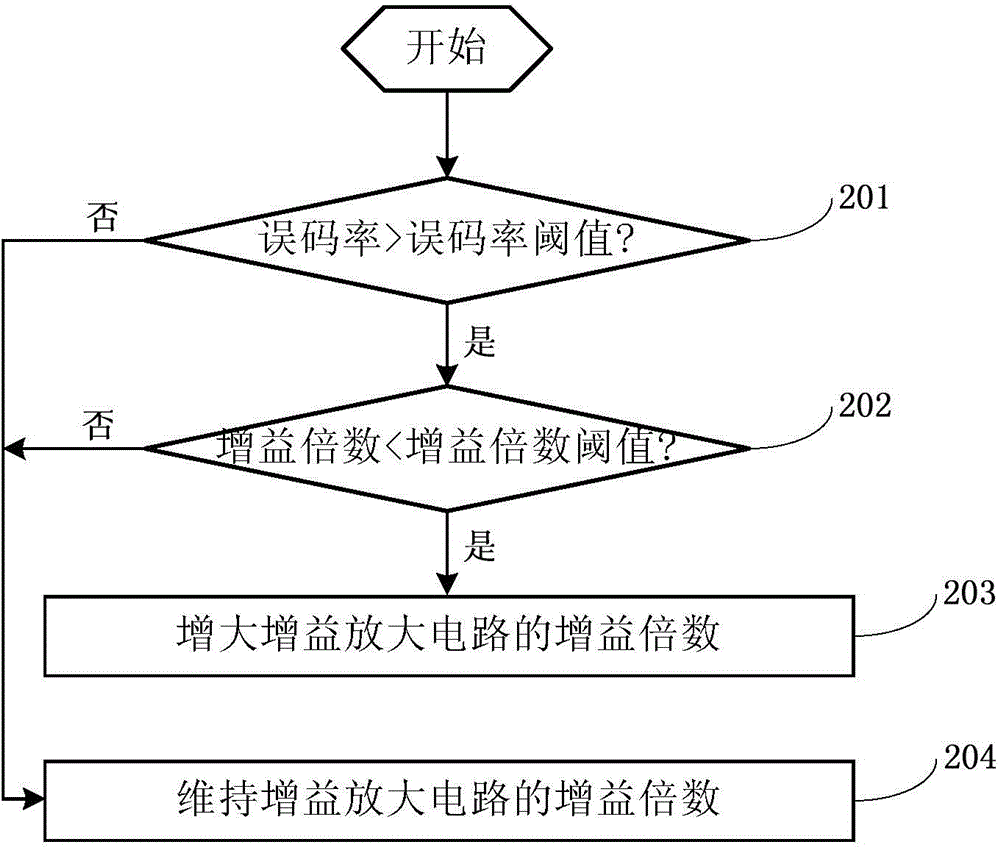
The invention discloses a method and system for adjusting parameters of a signal receiving circuit of a downhole repeater. The method comprises the following steps: detecting an error rate of a received signal; determining a gain multiple of a gain amplification circuit according to the error rate; and determining the parameters of an analog filter circuit and the parameters of a digital filter according to the gain multiple and carrier frequency that is set offline according to a test result. By adopting the method and the system disclosed by the invention, the downhole repeater can effectively inhibit wellsite electromagnetic interference and accurately capture weak useful signals to ensure normal work. When the error rate is too high, whether to increase the gain multiple or modify the carrier frequency to avoid the wellsite electromagnetic interference can be automatically determined, and corresponding processing measures are adopted to ensure that the repeater can correctly receive downhole electromagnetic signals to ensure the normal work of the entire system. Practice proves that the method and the system disclosed by the invention are good in electromagnetic interference suppression effect, small in size of a hardware circuit, small in hardware resource occupation, low in production cost, stable in functions and operation and are liable to realize by the existing technological level and processing technique at home.

Description

technical field [0001] The invention relates to the technical field of oil and gas development and drilling, in particular to a method for adjusting parameters of a signal receiving circuit of an downhole repeater, and also relates to a system for adjusting parameters of the signal receiving circuit of an downhole repeater. Background technique [0002] The electromagnetic measurement-while-drilling system is a key instrument used in the directional deflection process of horizontal well and directional well drilling. The downhole signal transmission repeater is installed between the downhole transmitter and the ground receiver of the electromagnetic measurement while drilling system, and is used to receive the electromagnetic signal of the downhole transmitter, and transmit the signal to the ground receiver after processing, thereby improving the signal strength received by the ground , so as to enhance the adaptability of the electromagnetic measurement-while-drilling syste...

Claims


Application Information

Patent Timeline
Patent Type & Authority Applications(China)
IPC IPC(8): H04B1/40
Inventor 陈晓晖宋朝晖王立双孙明光高炳堂杨春国胡越发孙连环
Owner CHINA PETROLEUM & CHEM CORP
Learn More