Wireless terminal test system

A wireless terminal and test system technology, applied in the direction of measurement device, antenna radiation pattern, measurement of electrical variables, etc., can solve the problems of bulky test system, high manufacturing cost, small scope of application, etc., to reduce manufacturing cost, easy to operate, Wide range of effects

Active Publication Date: 2016-11-23
GENERAL TEST SYST
View PDF3 Cites 17 Cited by
  • Summary
  • Abstract
  • Description
  • Claims
  • Application Information

AI Technical Summary

Problems solved by technology

[0004] However, the test speed of this system is slow, and because the distance between the test antenna and the DUT is required to be greater than the far-field distance, the test system is bulky, the manufacturing cost is high, and the scope of application is small.

Method used


Image

  • Wireless terminal test system
  • Wireless terminal test system
  • Wireless terminal test system

Examples


Embodiment Construction

[0020] Embodiments of the present invention are described in detail below, examples of which are shown in the drawings, wherein the same or similar reference numerals denote the same or similar modules or modules having the same or similar functions throughout. The embodiments described below by referring to the figures are exemplary only for explaining the present invention and should not be construed as limiting the present invention. On the contrary, the embodiments of the present invention include all changes, modifications and equivalents coming within the spirit and scope of the appended claims.

[0021] A test system for a wireless terminal according to an embodiment of the present invention will be described below with reference to the accompanying drawings.

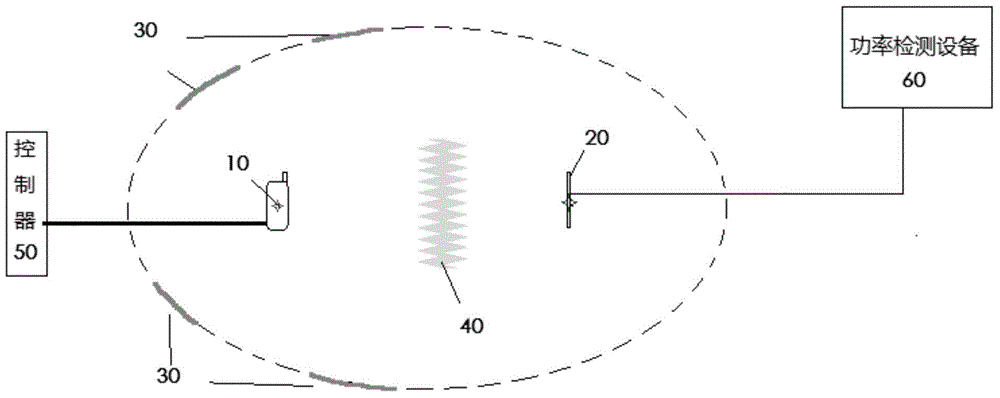
[0022] figure 1 It is a schematic structural diagram of a wireless terminal testing system according to another embodiment of the present invention. like figure 1 As shown, the wireless terminal testing system...


PUM


Abstract

The invention provides a wireless terminal test system, which comprises a tested piece, a test antenna, a reflecting surface, an absorbing screen, a controller and a power detection device, wherein the tested piece is the wireless terminal; the reflecting surface is used for carrying out total reflection on wireless signals transmitted by the tested piece; the absorbing screen is used for absorbing radio waves; the controller is connected with the tested piece for controlling the tested piece to transmit the wireless signals; the power detection device is used for detecting the power of the wireless signals received by the test antenna; the position relation among the tested piece, the test antenna and the reflecting surface is corresponding to the same ellipsoid; the tested piece and the test antenna are arranged at two focal points of the same ellipsoid respectively; the reflecting surface is arranged on the ellipsoid; and the absorbing screen is arranged on the straight line between the tested piece and the test antenna. The wireless terminal test system of the invention can improve the test efficiency and reduce the cost.

Description

technical field [0001] The invention relates to the technical field of testing, in particular to a testing system for wireless terminals. Background technique [0002] In the radiation performance test of wireless terminals, it is necessary to test the magnitude of radiation signals in multiple directions and the magnitude of receiving sensitivity in multiple radiation directions, and obtain the total radiation power and total radiation sensitivity through mathematical calculations. Since the antenna of a mobile wireless communication terminal is usually not a directional antenna, but radiates in all directions in space, when testing the wireless performance of a mobile terminal, the basic idea is to place the device under test at the center of a sphere, and use the test The antenna tests the strength of the signal at multiple positions on the spherical surface, and calculates the total radiation intensity after obtaining the test values ​​of all positions. [0003] At pres...

Claims


Application Information

Patent Timeline
Patent Type & Authority Applications(China)
IPC IPC(8): H04M1/24
CPCG01R29/10G01R29/0821H04B17/29G01R29/105
Inventor 漆一宏刘克峰于伟
Owner GENERAL TEST SYST
Why Eureka
Try Eureka