
Clamp connection structure capable of being disassembled and assembled quickly

A connection structure and fast technology, applied in the direction of electrical components, casings/cabinets/drawer parts, electrical equipment casings/cabinets/drawers, etc., can solve the problems of inconvenient disassembly, reduced matching strength, inconvenient disassembly and assembly, etc. , to achieve the effect of ensuring convenience, high structural strength and strengthening assembly strength

Inactive Publication Date: 2016-11-23
上海脉慈医疗器械有限公司
View PDF2 Cites 0 Cited by
  • Summary
  • Abstract
  • Description
  • Claims
  • Application Information

AI Technical Summary

Problems solved by technology

In the previous product structure, the assembly of plastic parts mostly adopts a full snap-on design, typically the full snap-on design of the back cover of a mobile phone. The disadvantage of this design is that it is inconvenient to disassemble, and if you want to further increase the convenience of disassembly , it needs to be at the cost of reducing the matching strength, (because this design wants to increase the convenience of disassembly, the method of reducing the thickness of the buckle and reducing the draft angle of the buckle will lead to a reduction in the strength of the fit), that is, the improvement of the convenience of disassembly It is difficult to improve the matching strength at the same time. The matching form of screw holes and screws has the disadvantage of inconvenient disassembly and assembly.
That is, the product is technically faced with the problem that it is difficult to ensure the improvement of disassembly convenience and the improvement of matching strength at the same time

Method used


Image

  • Clamp connection structure capable of being disassembled and assembled quickly
  • Clamp connection structure capable of being disassembled and assembled quickly
  • Clamp connection structure capable of being disassembled and assembled quickly

Examples


Embodiment 1

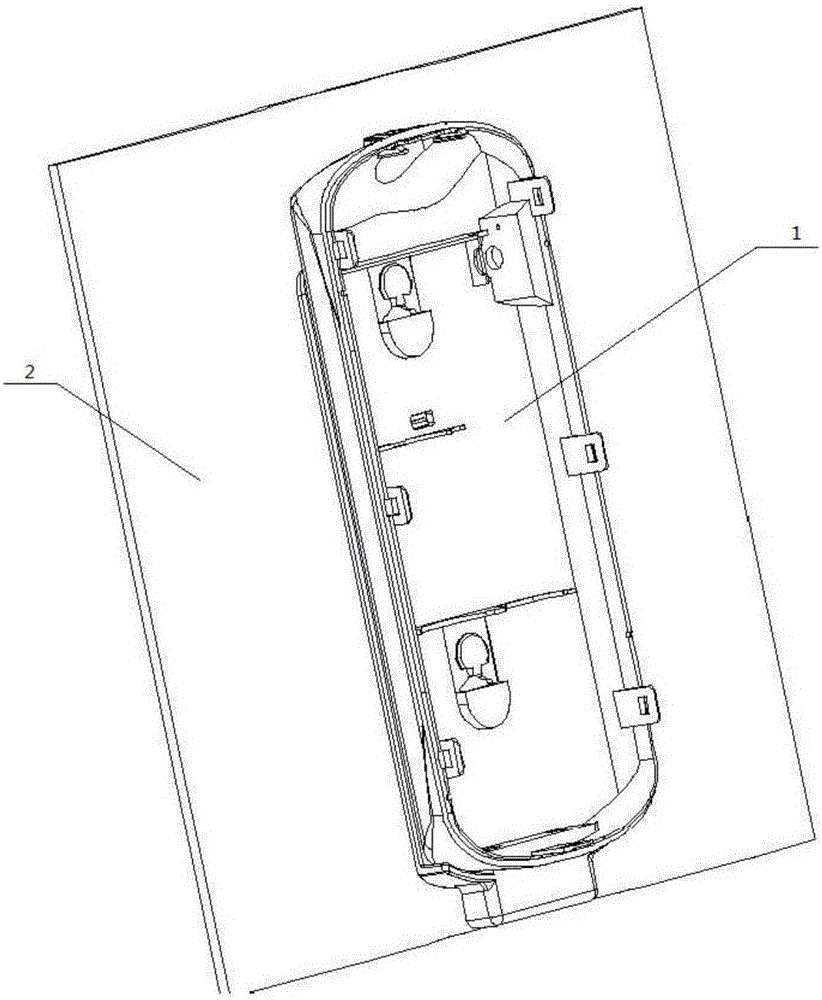
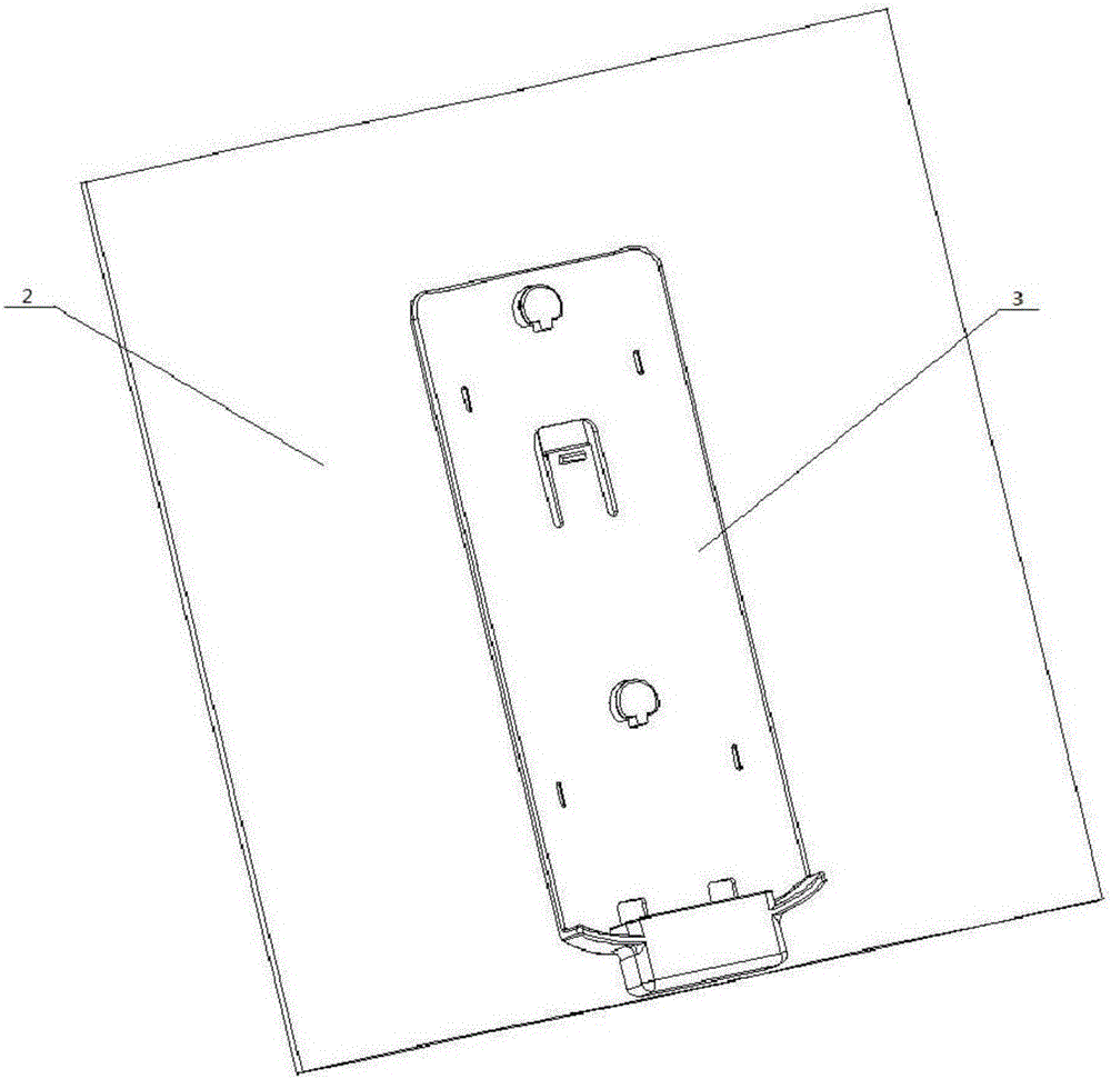
[0046] Such as figure 1 , 2 As shown, the overall diagram of a quick-detachable clamping structure includes a main body 1, a wrapping cloth 2, and a bottom plate 3. The wrapping cloth is made of soft fibers and is fixedly connected with the bottom plate with glue. The product needs to connect the main body and the wrapping The cloth is detachably connected, and the present invention is assembled by sticking the bottom plate on the wrapping cloth, and then assembling the bottom plate and the main body through snap-fit ​​mounting and dismounting.

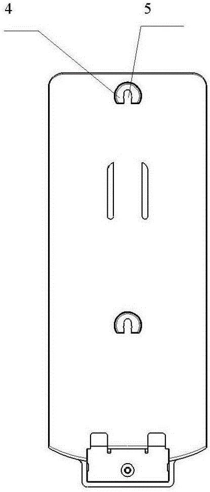
[0047] Base structure such as Figure 3-7 As shown, there is a T-shaped protruding structure and a shrapnel 6 structure on the bottom plate, and buckles 7 are arranged on the shrapnel, and the T-shaped protruding structure is formed by a vertical combination of a T-pillar 5 and a T-surface 4 . T-shaped protruding structures such as Figure 8-11 shown.

[0048] Body 1 is structured like Figure 12-15 As shown, there are T-surface ...


PUM


Abstract

The invention discloses a clamping structure that can be quickly disassembled and assembled, and belongs to the field of assembly structure design. The invention solves the problem that in the field of assembly structure between plastic parts, it is difficult to ensure the improvement of the matching strength and the improvement of disassembly convenience at the same time. For example, the assembly structure of the full snap-on mobile phone back cover is faced with the problem of strengthening the snap-fit ​​assembly strength. At the same time, the problem of dismounting convenience will be reduced, and the present invention solves this problem well. The specific technical method is simply to introduce the T-shaped protruding structure (4, 5) and the T surface matching groove ( 8) and the T-pillar chute (9) structure, use this matching structure to control the factors of the matching strength, and at the same time introduce the matching structure of the shrapnel with buckle (6), buckle (7) and buckle groove (10) , using this matching structure to control the factors of disassembly strength, since the two structures are independent and not affected, the combination strength and disassembly convenience can be improved at the same time.

Description

technical field [0001] The invention belongs to the field of assembly structure design, and in particular relates to a clamping structure that can be quickly disassembled and assembled. Background technique [0002] In the varicose vein treatment instrument product, the main body needs to be fixed on the base plate, and the disassembly between the two can be realized (the base plate is bonded on the wrapping cloth, which cannot be disassembled, and the wrapping cloth can be wound and fixed on the consumer’s leg. The focus of the present invention is The assembly structure between the main body and the bottom plate, the introduction of the wrapping cloth is to illustrate an example of the actual working environment of the assembly structure), the material of the main body and the bottom plate is hard plastic, and the detachable assembly structure of the main body and the bottom plate requires on the one hand To achieve the detachability of the assembly, on the other hand, it ...

Claims


Application Information

Patent Timeline
IPC IPC(8): H05K5/02
CPCH05K5/0204H05K5/0217
Inventor 黄怡
Owner 上海脉慈医疗器械有限公司
Learn More