Fastening parts and rod-shaped parts for fastening parts
A technology for fastening parts and rod-shaped parts, which is applied to threaded fasteners, connecting members, screws, etc., can solve problems such as lightweight obstructions, and achieve superior strength and stress corrosion cracking resistance
- Summary
- Abstract
- Description
- Claims
- Application Information
AI Technical Summary
Problems solved by technology
Method used
Image
Examples
Embodiment approach 1
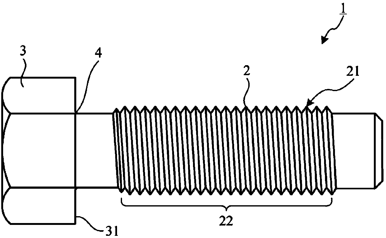
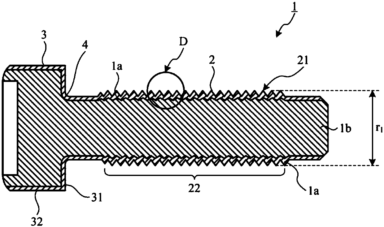
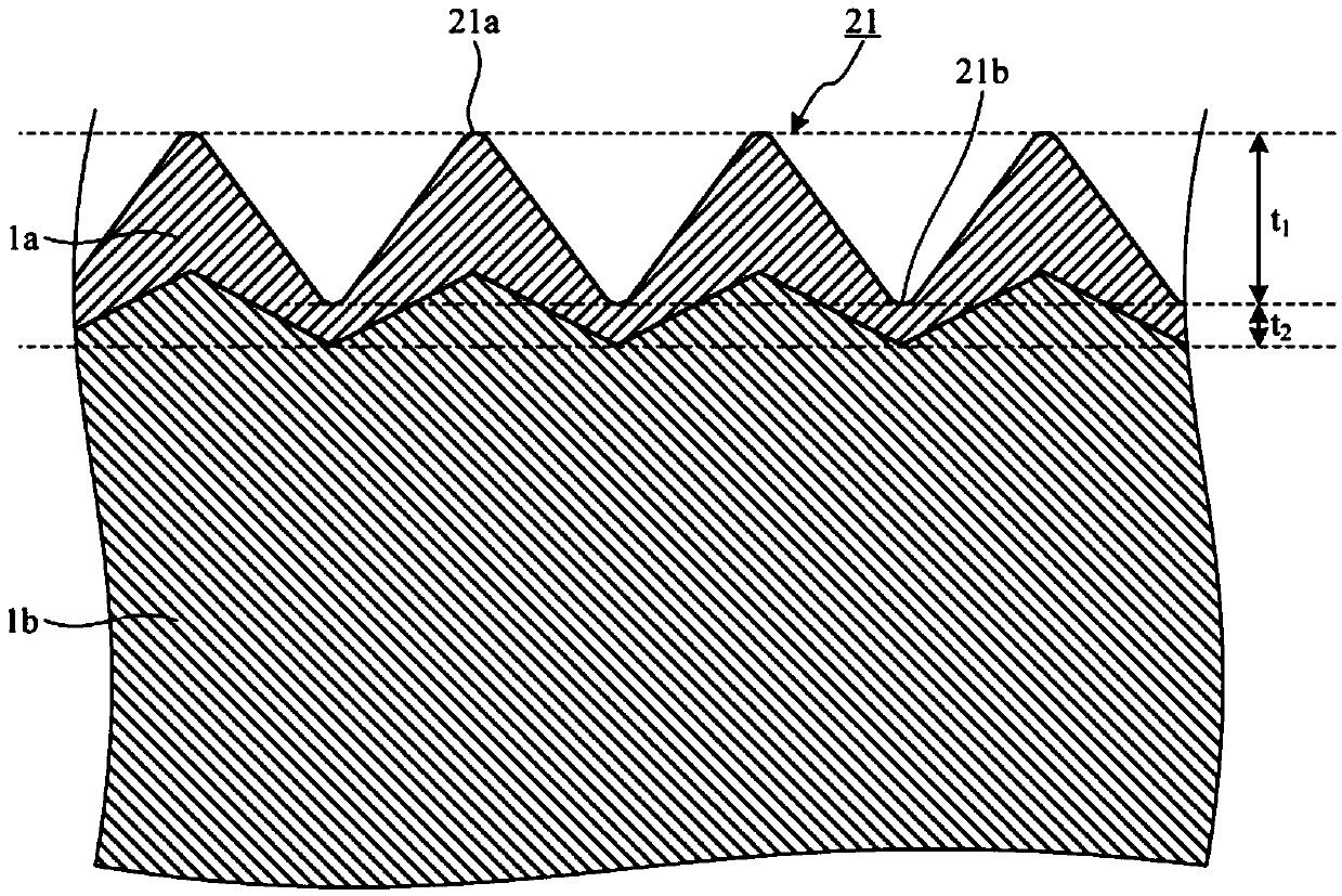
[0051] figure 1 It is a side view which shows the structure of the fastening member which concerns on Embodiment 1 of this invention. figure 2 Yes figure 1 The direction of the fastening part shown through its length ( figure 1The cross-sectional view of the central axis of the left-right direction). The fastening member 1 shown in these figures is a bolt (a type of externally threaded member) formed of a cladding material formed by joining two aluminum (Al) alloys different from each other. The fastening part 1 includes: a shaft part 2, which is cylindrical; a head 3, which is arranged in the axial direction of the shaft part 2 ( figure 1 and the neck 4 constituting the boundary between the shaft portion 2 and the head 3. The shaft portion 2 has a threaded portion 22 having a threaded portion 21 formed on its surface. in addition, figure 1 The shown shape of the head 3 (hexagonal shape) is only an example, and other shapes (hexagonal meson shape, cylindrical shape, fla...
Embodiment approach 2
[0064] Figure 5 It is a plan view showing the structure of the fastening member according to Embodiment 2 of the present invention. Image 6 Yes Figure 5 The A-A line sectional view. The fastening member 5 shown in these figures is a nut (a type of internally threaded member) made of a coating material formed by joining two different aluminum alloys together. The fastening member 5 has a hollow cylindrical shape, and a thread 52 is formed on the inner surface of a hole 51 formed in the center. in addition, Figure 5 The shown shape of the fastening part 5 (hex nut) is only an example, and nuts having other shapes (flange nut, cap nut, long nut, etc.) can also be realized.
[0065] The fastening member 5 includes a first alloy portion 5a and a second alloy portion 5b each formed of two different aluminum alloys. The first alloy portion 5 a forms an annular shape on the surface of the thread 52 , which is a portion in contact with a member to be fastened and connected. T...
Embodiment approach 3
[0075] Figure 9 It is a side view which shows the structure of the fastening member which concerns on Embodiment 3 of this invention. Figure 10 Yes Figure 9 The direction of the fastening part shown through its length ( Figure 9 The cross-sectional view of the central axis of the left-right direction). The fastening member 6 shown in these figures is a rivet made of a cladding material formed by joining two kinds of aluminum alloys different from each other. The fastening member 6 includes a cylindrical shaft portion 7, which is arranged in the height direction of the cylinder forming the shaft portion 7 ( Figure 9 The head 8 at one end of the left-right direction) and the neck 9 constituting the boundary between the shaft portion 7 and the head 8 . in addition, Figure 9 The shown shape of the head 8 (round head) is only one example, other shapes are also possible (flat head, etc.).
[0076] The fastening member 6 includes a first alloy portion 6a and a second allo...
PUM
| Property | Measurement | Unit |
|---|---|---|
| thickness | aaaaa | aaaaa |
| thickness | aaaaa | aaaaa |
| Vickers hardness | aaaaa | aaaaa |
Abstract
Description
Claims
Application Information
 - R&D Engineer
- R&D Manager
- IP Professional
- Industry Leading Data Capabilities
- Powerful AI technology
- Patent DNA Extraction
Browse by: Latest US Patents, China's latest patents, Technical Efficacy Thesaurus, Application Domain, Technology Topic, Popular Technical Reports.
© 2024 PatSnap. All rights reserved.Legal|Privacy policy|Modern Slavery Act Transparency Statement|Sitemap|About US| Contact US: help@patsnap.com


