Sealed cable entry devices passing through the outer and inner walls of the containment vessel of a nuclear power plant

A technology for introducing devices and sealing cables, which is applied in the field of electrical engineering and can solve problems such as damage to insulation sheaths

Active Publication Date: 2018-04-06
阿托门纳哥普勒科特工程合资(控股)公司
View PDF6 Cites 0 Cited by
  • Summary
  • Abstract
  • Description
  • Claims
  • Application Information

AI Technical Summary

Problems solved by technology

When using stiffer wires with larger diameters that cannot be bent in the spanning region between the inner and outer walls of the containment when one end is displaced relative to the other, the wire exit in the compensator will experience a torsional moment and squeeze. Press the supporting element at the outlet of the conductor in the pipe, as a result, damage to the insulation sheath

Method used


Image

  • Sealed cable entry devices passing through the outer and inner walls of the containment vessel of a nuclear power plant
  • Sealed cable entry devices passing through the outer and inner walls of the containment vessel of a nuclear power plant
  • Sealed cable entry devices passing through the outer and inner walls of the containment vessel of a nuclear power plant

Examples


Embodiment Construction

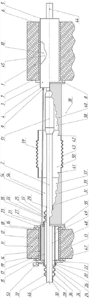
[0026] The sealed cable lead-in device passing through the outer wall and inner wall of the containment vessel of a nuclear power plant includes a first penetration assembly composed of embedded sleeves 3 fixed in the reinforced concrete inner wall 1, and the cables 2 in the penetration assembly are stable. The inner wall 1 is arranged in a sealed dome shape with an average thickness of about 1.2 meters, and its function is to ensure that the remaining internal pressure can be preserved when an accident occurs in the containment. The ends 4 and 5 of the sleeve 3 protrude a little from the plane of the outer 6 and inner 7 surfaces of the inner wall 1 . The end 4 of the bushing 3 on the side of the inner surface 7 of the wall 1 is fitted with a transition flange 8 enabling a rigid and tight connection of the bushing 3 in the wall 1 . A pipe joint 9 communicating with the cavity 10 of the sleeve 3 is also installed at the end 4 of the sleeve 3 . A hole 12 coaxial with the casin...


PUM


Abstract

The invention relates to the field of electrical engineering, in particular to a device for introducing circuit sealing into the sealing area of ​​a nuclear power plant's multi-layer containment shell. The device may be used in penetrations through internal and external walls that are susceptible to displacement relative to each other by earthquakes or thermal expansion of the walls and penetrations. The object of the present invention is to improve the reliability of sealed cable entries using difficult-to-bend high voltage wires. In order to achieve the proposed purpose, there is provided a sealed cable entry device passing through the outer wall and inner wall of the containment vessel of a nuclear power plant, which includes an embedded sleeve (3) arranged in the inner wall (1), said sleeve The entry portion (44) of the cable (2) is fixed rigidly inside. A device for compensating relative movement between the cable (2) and the outer wall (11) is installed on the outer wall (11) along the axis of the bushing (3). The compensating device has a pipe (19) with a bellows (24) on the outer end (20) of the pipe and on the other end (21) of the pipe on the inner surface (18) of the outer wall (11). A second similar bellows (25) is mounted symmetrically. The active ends (30) and (31) of the bellows (24) and (25) are set in a conical shape, and their inner surfaces (28) and (29) are supports for the outlet portion (46) of the cable (2), said The outlet portion (46) of the cable (2) is freely disposed within the duct (19) with a gap (47) relative to the inner surface (49) of the duct (19). The gap 47 between the sheath (48) of the outer surface of the cable (2) and the inner surface (49) of the pipe (19) is selected according to design calculations. The gap (47) should not be less than the maximum orthogonal thermal-seismic displacement amplitude in one plane of the inner wall (1) relative to the outer wall (11) and the change in coaxial position of the cable (2) in the duct (19).

Description

technical field [0001] The present invention relates to the field of electrical engineering, and in particular to a device for introducing circuit sealing into the sealing area of ​​a nuclear power plant's multi-layer containment vessel, which can be opposed to each other when passing through, which is easily affected by earthquakes or thermal expansion of walls and penetrations Used in penetrations of displaced interior and exterior walls. Background technique [0002] A sealed power entry through the reinforced concrete walls of the containment vessel of a nuclear power plant is known, which consists of a sleeve with a biological shield and electrical leads inside (cf. USSR Invention Certificate No. 1551142 of 14.04.1988, State Classification No.: H01B 17 / 26). [0003] The sealed cable entry can only lead electrical conductors into the containment vessel of a nuclear power plant having a reinforced concrete wall. In order to improve the safety of nuclear power plant oper...

Claims


Application Information

Patent Timeline
Patent Type & Authority Patents(China)
IPC IPC(8): G21C13/04H02G3/22
CPCG21C13/04H02G3/22G21C17/116G21C13/036Y02E30/30G21C13/028
Inventor 马拉特雷纳多维奇·慕斯塔芬亚历山大格里戈耶维奇·格拉斯门科凡冷廷伊万诺维奇·萨帕里科夫尼古拉阿纳托耶维奇·伊万诺夫戈那迪亚历克斯维奇·诺维科夫阿尔诺德博里斯维奇·提克米诺夫伊万米开诺维奇·考斯托夫
Owner 阿托门纳哥普勒科特工程合资(控股)公司
Why Eureka
Try Eureka