Bottom liquid drainage device

A discharge device and bottom liquid technology, applied in liquid separation, liquid separation auxiliary equipment, dispersed particle separation, etc., can solve the problems of large discrete structure, inconvenient installation and debugging, etc.

Inactive Publication Date: 2016-11-30
刘晓明
View PDF2 Cites 0 Cited by
  • Summary
  • Abstract
  • Description
  • Claims
  • Application Information

AI Technical Summary

Problems solved by technology

[0002] In the production, storage and transportation of liquid and gas products, there will be technical requirements for separating and discharging the bottom liquid. There is a measuring device directly installed on the storage tank to measure the interface change of the two-phase liquid and control the valve switch, such as the case of CN201420164942; such a structure Large discreteness, inconvenient to install and debug

Method used


Image

  • Bottom liquid drainage device

Examples


Embodiment Construction

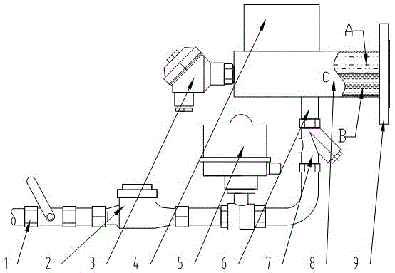
[0009] Such as figure 1 As shown, the right end of the pipe joint (9) is connected to the bottom liquid outlet pipe of the storage tank, and the left end is connected to the measuring tube (8), which is responsible for the pipe connection and the fixing of the entire device. In the measuring tube (8), the upper part is liquid A with low density, the bottom is liquid B with high density, and the two-phase liquid interface C; the bottom of measuring tube (8) is connected with discharge pipe (6), measuring tube (8) The interface measurement device (3) and the electric control box (4) are also installed on it; the discharge pipe (6) has a filter (7), an automatic control valve (5), a metering detection device (2) and a manual valve ( 1).

[0010] There is a signal remote transmission communication interface in the electric control box (4), which can communicate with the central control equipment in a network. When working, the control circuit processes various working signals of...


PUM


Abstract

The invention discloses a bottom liquid drainage device. The structure of the bottom liquid drainage device is simple and practical. The bottom liquid drainage device is directly arranged on a storage tank bottom liquid drainage pipe outlet, and is provided with a measurement channel, a discharge channel, a measuring device used for measuring and identifying the change of two-phase liquid interface, and an autocontrol valve. Whole set level is high; production, installation, application, and maintenance are convenient; popularization and application of bottom liquid drainage equipment are promoted; and technical progress of storage tank technology is promoted.

Description

technical field [0001] The invention relates to a two-phase liquid or gas-liquid separation device, in particular to a bottom liquid discharge device installed on a bottom liquid outlet pipe of a storage tank. Background technique [0002] In the production, storage and transportation of liquid and gas products, there will be technical requirements for separating and discharging the bottom liquid. There is a measuring device directly installed on the storage tank to measure the interface change of the two-phase liquid and control the valve switch, such as the case of CN201420164942; such a structure Large discrete, inconvenient installation and debugging. There is also a small tank installed on the side of the large storage tank. In the small tank, there is a measuring device for measuring the change of the two-phase liquid interface and controlling the valve switch, such as the patent number: CN201420058376 case; the small tank needs to be installed on the ground. The liqu...

Claims


Application Information

Patent Timeline
Patent Type & Authority Applications(China)
IPC IPC(8): B01D17/032B01D45/02B01D17/12
Inventor 刘晓明
Owner 刘晓明
Why Eureka
Try Eureka