Special clamp for hinge seat pin hole of clutch pressure disc

A special fixture and clutch technology, used in clamping, manufacturing tools, drilling/drilling equipment, etc., can solve the problems that fixtures cannot meet processing requirements, reduce production efficiency, and affect production rhythm, so as to improve production efficiency and reduce The effect of labor intensity and stable performance of pin holes

Active Publication Date: 2016-11-30
山东理工远航教育服务有限公司
View PDF5 Cites 2 Cited by
  • Summary
  • Abstract
  • Description
  • Claims
  • Application Information

AI Technical Summary

Problems solved by technology

[0003] At present, the traditional processing method of the hinge seat pin hole is to put the clutch pressure plate on the working table of the drilling machine first, and then drill the hole after clamping, positioning and pressing. After drilling the hole, loosen the nut, and then place the clutch pressure plate Put it on another machine tool, clamp it again, and then ream it

Method used


Image

  • Special clamp for hinge seat pin hole of clutch pressure disc
  • Special clamp for hinge seat pin hole of clutch pressure disc
  • Special clamp for hinge seat pin hole of clutch pressure disc

Examples


Embodiment 1

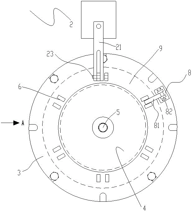
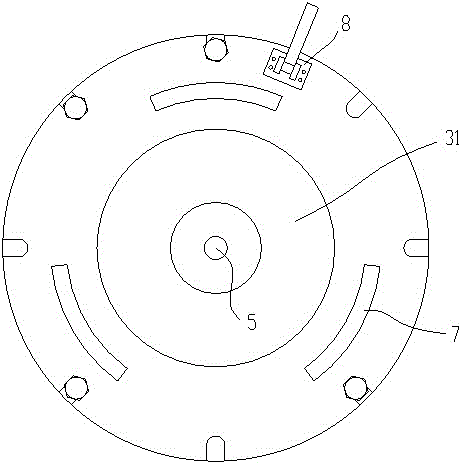
[0019] like Figure 1-3 As shown, a special fixture for the pin hole of the hinge seat of the clutch pressure plate, including: a rotary indexing table 1 of the machine tool, a guide device 2, a support frame 3, a pressure plate 4 and a screw rod 5, and the guide device 2 is arranged on the rotary indexing table of the machine tool. One side of the workbench 1 is used for positioning and guiding the hinge seat 6 on the clutch pressure plate 9. The guide device 2 includes a pair of guide arms 21 and a guide rail 22 for the clutch pressure plate 9 hinge seat 6 to guide. The guide arm 21 is arranged on the guide rail 22 and can move back and forth, and the guide arm 21 is provided with a guide hole 23 .

[0020] The rotary indexing table 1 of the machine tool is provided with a T-shaped slot, and the rotatable support frame 3 is connected with the rotary indexing table 1 of the machine tool through the screws arranged in the T-shaped slot. The support frame 3 is provided with Po...

Embodiment 2

[0022] On the basis of Embodiment 1, the special fixture of the present invention also includes a pre-positioning device 8, and the pre-positioning device 8 is fixed on the support frame 3 for when the clutch pressure plate 9 is installed on the When supporting the frame 3, the clutch pressure plate 9 is pre-positioned. The pre-positioning device 8 includes a positioning rod 81 and a connecting frame 82, the positioning rod 81 is movably connected to the connecting frame 82, and the positioning rod 81 is installed on the joint between two adjacent hinge seat units of the clutch pressure plate. within the void.

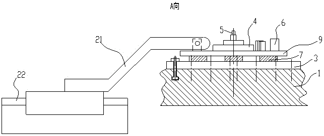
[0023] like Figure 4 As shown, the processing process of using the special fixture of the present invention to process the pin holes of the clutch pressure plate hinge seat is as follows: first use the drilling guide device 2 to position and guide the clutch pressure plate hinge seat, and after the drill bit 10 performs the drilling process on the hinge seat , the d...


PUM


Abstract

The invention relates to a special clamp for a hinge seat pin hole of a clutch pressure disc. The special clamp comprises a machine tool rotation graduated table, a guiding device, a supporting frame, a pressing plate and a screw. The guiding device is arranged on one side of the machine tool rotation graduated table and used for enabling a hinge seat to perform positioning guiding, the machine tool rotation graduated table is provided with a T-shaped groove, the rotatable supporting frame is connected with the machine tool rotation graduated table through the screw in the T-shaped groove, the supporting frame is provided with a positioning boss, the clutch pressure disc is installed on the supporting frame through the positioning boss, and the pressing plate is installed on the upper portion of the clutch pressure disc and fastens the clutch pressure disc through the screw on the positioning boss. The guiding device can perform positioning guiding on a drill, the drilling precision is met well, and the hinge seat pin hole of the clutch pressure disc is stable in performance; the supporting frame performs graduated rotation on the clutch pressure disc, hole drilling and reaming can be finished simultaneously through one-time clamping, labor intensity is lowered, and production efficiency is improved.

Description

technical field [0001] The invention relates to a special fixture for a clutch pressure plate, in particular to a special fixture for a hinge seat pin hole of a clutch pressure plate. Background technique [0002] The hinge seat pin hole in the clutch pressure plate is a key part of the clutch assembly. Its geometric state and dimensional accuracy often determine the effect of the clutch after separation, thus affecting the running state, running effect and smooth shifting of the vehicle during operation. every aspect. [0003] At present, the traditional processing method of the hinge seat pin hole is to put the clutch pressure plate on the working table of the drilling machine first, and then drill the hole after clamping, positioning and pressing. After drilling the hole, loosen the nut, and then place the clutch pressure plate Put it on another machine tool, clamp it again, and then ream it. By analogy, the processing of each hinge seat pin hole is completed sequentiall...

Claims


Application Information

Patent Timeline
IPC IPC(8): B23Q3/06B23B49/00
CPCB23B49/00B23B2270/34B23Q3/062
Inventor 王庆薛惠福薛惠珍薛塬东薛塬尊梁爽宁涛
Owner 山东理工远航教育服务有限公司
Why Eureka
Try Eureka