Automatic length fixing floating support device for machining crossover coupling

A floating support and automatic length-fixing technology, which is applied in positioning devices, clamping devices, thread cutting devices, etc., can solve the problems of high scrap rate, low processing accuracy, and low efficiency, and achieve high production efficiency and satisfactory processing accuracy. The effect of precision problems

Inactive Publication Date: 2015-02-11
SHENYANG LIGONG UNIV
View PDF6 Cites 1 Cited by
  • Summary
  • Abstract
  • Description
  • Claims
  • Application Information

AI Technical Summary

Problems solved by technology

[0003] The purpose of the present invention is to provide an automatic fixed-length floating support device for the technical problems existing in the processing of commonly used 610-2

Method used


Image

  • Automatic length fixing floating support device for machining crossover coupling
  • Automatic length fixing floating support device for machining crossover coupling
  • Automatic length fixing floating support device for machining crossover coupling

Examples


Embodiment Construction

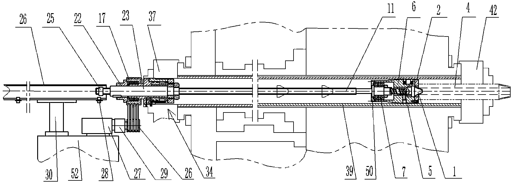
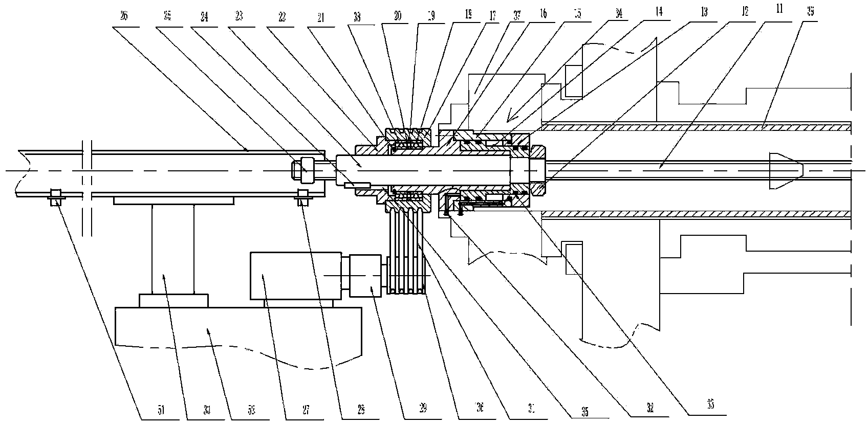
[0020] An automatic fixed-length floating support device for processing conversion joints, including a floating support mechanism, a lead screw 11, a screw nut 23, a screw axial movement drive mechanism, a screw nut rotation drive mechanism and a switch bracket assembly, characterized in that:

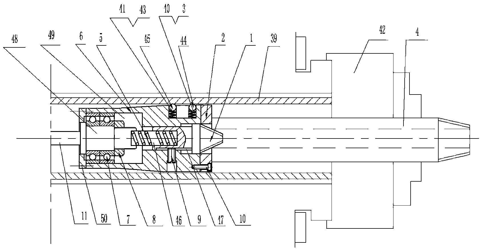
[0021] The floating support mechanism is installed in the front part of the main shaft drawing tube 39, and the floating support mechanism includes the top 1, the positioning end cover 2 and the guide sleeve 6. The positioning end cover 2 is fixedly connected with the guide sleeve 6 through a plurality of bolts 10 . Three first cylindrical holes 40 and three second cylindrical holes 41 are respectively and equidistantly formed on the outer surface of the front end of the guide sleeve 6 at two locations. The first springs 3 are respectively installed in the three first cylindrical holes 40 , and the second springs 43 are respectively installed in the three second cylindrical holes 41 . ...


PUM


Abstract

The invention discloses an automatic length fixing floating support device for machining a crossover coupling. The device comprises a floating support mechanism, a lead screw, a nut, a lead screw axial-movement driving mechanism and a nut rotation driving mechanism, wherein the floating support mechanism mainly comprises a tip, a positioning cover, a guide sleeve and a third spring, which are assembled; the front end of the lead screw is pressed against the third spring; the lead screw axial-movement driving mechanism mainly comprises an oil cylinder body, an inner oil cylinder sleeve, an oil cylinder end cover, an oil cylinder piston and a pressing nut, which are assembled; the nut is in threaded connection with the rear end of the lead screw; the nut rotation driving mechanism comprises a motor, a speed reducer, a first belt pulley and a second belt pulley; an inner cavity of the first belt pulley is arranged on the rear part of the inner oil cylinder sleeve after a second ball bearing is arranged in the inner cavity of the first belt pulley; the nut is arranged in center holes of a rear belt pulley end cover and the inner oil cylinder sleeve, and is in key connection with the rear belt pulley end cover. According to the device, the machining accuracy and production efficiency of a workpiece can be effectively improved, and the reject ratio is lowered.

Description

technical field [0001] The invention belongs to the technical field of automatic cutting equipment, and in particular relates to an automatic fixed-length floating support device for processing conversion joints. Background technique [0002] Oilfields often use adapters of different lengths for drilling wells with different depths, and the lengths of 610-2000 mm are commonly used. Generally, both ends of the conversion joint have internal and external threads respectively, and the internal and external threads at both ends have design requirements such as coaxiality. Usually processed on CNC pipe machine tools, because only one end can be positioned, the other end cannot be positioned, or one end is positioned, the other end is not positioned automatically but manually adjusted; and because of the different lengths of the joints, the machine tool cannot quickly adapt to parts of different lengths Due to the above two reasons, problems such as low processing precision, low ...

Claims


Application Information

Patent Timeline
IPC IPC(8): B23G1/44B23G1/02
CPCB23G1/44B23Q3/12B23Q2703/10
Inventor 隋连香高帅陆子洋薛明范飞卢明远于林池
Owner SHENYANG LIGONG UNIV
Why Eureka
Try Eureka