Light-emitting device

A light-emitting device and laser technology, applied in lighting devices, optics, light sources, etc., can solve problems such as changes in intensity distribution, offsets in the positional relationship between light sources and lens elements, and achieve an effect that is not easy to change

Active Publication Date: 2016-11-30
NICHIA CORP
View PDF8 Cites 3 Cited by
  • Summary
  • Abstract
  • Description
  • Claims
  • Application Information

AI Technical Summary

Problems solved by technology

Therefore, if the collimator lens array is mounted with a slight rotation from a predetermined orientation, there is a possibility that the positional relations

Method used


Image

  • Light-emitting device
  • Light-emitting device
  • Light-emitting device

Examples


Embodiment approach 1

[0033] [Light-emitting device according to Embodiment 1]

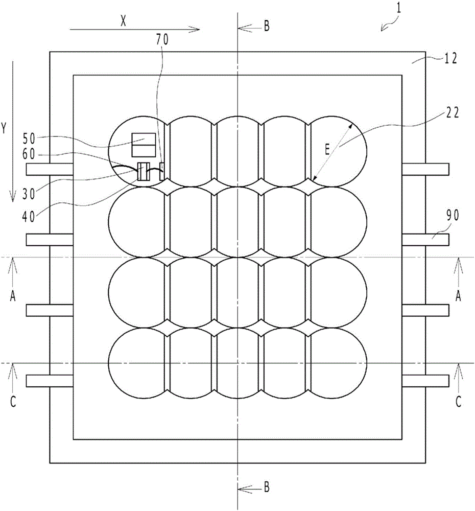
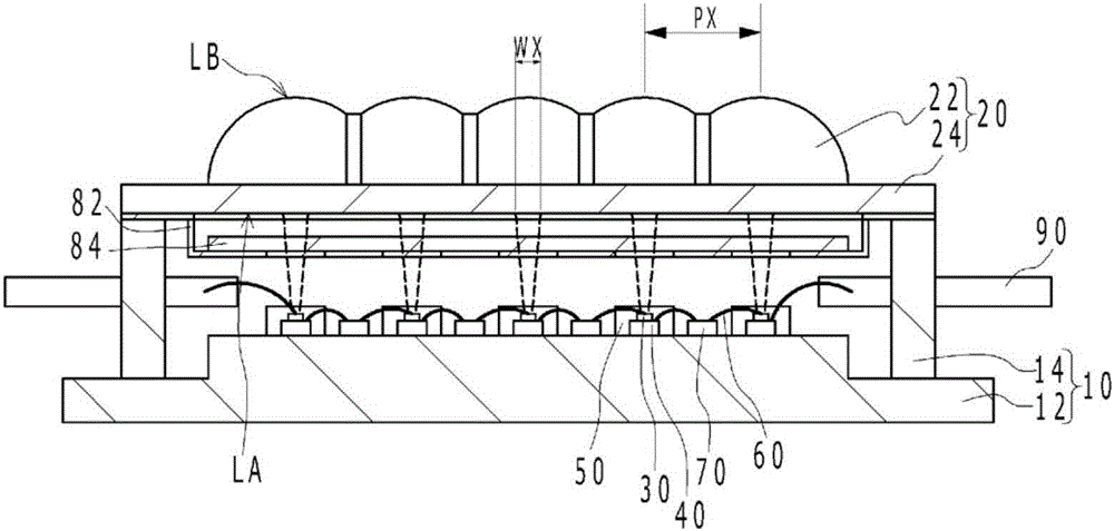
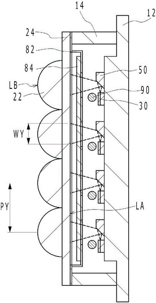
[0034] Figure 1A It is a schematic plan view of the light emitting device according to the first embodiment. in addition, Figure 1B yes Figure 1A A-A sectional view in, Figure 1C yes Figure 1A The B-B sectional view in, Figure 1D yes Figure 1A C-C sectional view in . exist Figure 1A In FIG. 2 , the semiconductor laser element 30 and the like disposed below the uppermost left lens portion are shown transparently for easy understanding. Such as Figure 1A to Figure 1D As shown, the light emitting device 1 according to Embodiment 1 includes: a substrate 10; a lens array 20 having a plurality of lens portions 22 in a matrix; and a plurality of semiconductor laser elements 30 arranged on the substrate 10, and a plurality of semiconductor laser elements. The element 30 emits laser light respectively, and each laser light has a beam shape with a wider width in the column direction than in the row direction on eac...

Embodiment approach 2

[0068] [Light-emitting device 2 according to Embodiment 2]

[0069] Figure 6A is a schematic plan view of a light emitting device according to Embodiment 2, Figure 6B yes Figure 6A M-M sectional view in, Figure 6C yes Figure 6A The N-N section view in, Figure 6D yes Figure 6A The O-O section view in . exist Figure 6A In FIG. 2 , the semiconductor laser element 30 and the like disposed below the uppermost left lens portion are shown transparently for easy understanding. Such as Figure 6A to Figure 6D As shown, in the light-emitting device 2 according to Embodiment 2, the plurality of lens arrays 20A, 20B, 20C, and 20D are arranged in the column direction (Y direction in FIG. 1 ), and the plurality of lens arrays 20A, 20B, 20C, and 20D are arranged in the row direction The direction (X direction in FIG. 1 ) is different from the light-emitting device 1 according to Embodiment 1 in that it has a plurality of lens portions 22 . Even according to Embodiment 2, si...

Embodiment approach 3

[0070] [Light-emitting device 3 according to Embodiment 3]

[0071] Figure 7 A schematic plan view of a light emitting device 3 according to Embodiment 3 is shown. Figure 7 The outer edge of the concave portion 82b is indicated by a dotted line. In addition, in Figure 7 In , hatching is applied to the area where the lens array 20 is fixed to the sealing member 80 by the adhesive. Such as Figure 7 As shown, in the light emitting device 3 , the lens array 20 includes the connecting portion 24 connecting the lens portions 22 to each other, and is fixed to the sealing member 80 at the connecting portion 24 with an adhesive. The sealing member 80 has a concave portion 82 b that is recessed toward a region of the base body 10 on which the plurality of semiconductor laser elements 30 are placed. The lens array 20 has a through-hole F inside the concave portion 82b in plan view, and is fixed to the sealing member 80 with an adhesive outside the concave portion 82b.

[0072] ...


PUM


Abstract

The invention provides a light-emitting device in which no significant deviation may occur in a positional relationship between the light sources and the lens elements when the collimator lens array is mounted only slightly rotated from a prescribed direction, and, consequently, an intensity distribution of light emitted from the collimator lens array may not change. The light-emitting device includes a substrate; a lens array having a plurality of lens sections in a matrix pattern; and a plurality of semiconductor laser elements disposed on the substrate. Each of the semiconductor laser elements emits a respective laser beam, each laser beam having a beam shape with a greater width in a column direction than in a row direction on a light incident surface of each respective lens section. The lens sections have an inter-vertex distance in the row direction that is smaller than both (i) a maximum outer diameter of each of the lens sections, and (ii) an inter-vertex distance in the column direction. A curvature of the lens sections in the row direction is the same as a curvature of the lens sections in the column direction.

Description

technical field [0001] The present invention relates to light emitting devices. Background technique [0002] There is known a light source device that collimates light emitted from a plurality of light sources with a collimator lens array (see Patent Document 1). [0003] Patent Document 1: Japanese Patent Laid-Open No. 2014-102367. [0004] However, in the conventional light source device described above, each lens element constituting the collimator lens array has a plurality of curvatures depending on the cross-sectional shape of the laser light incident on each lens element. Therefore, if the collimator lens array is mounted slightly rotated from a predetermined orientation, the positional relationship between the light source and the lens elements may shift greatly, and the intensity distribution of light emitted from the collimator lens array may change. Contents of the invention [0005] The above-mentioned problems can be solved by the following means, for examp...

Claims


Application Information

Patent Timeline
IPC IPC(8): F21K9/20F21K9/69F21V5/04F21Y115/30
CPCF21V5/04F21Y2115/30F21K9/00F21K9/69G02B19/0057G02B3/0056H01S5/405H01S5/02216H01S5/4018H01S5/0071F21V5/007H01S5/02345H01S5/02255H01S5/02253H01S5/4025
Inventor 清田征尔高鹤一真冈久英一郎
Owner NICHIA CORP
Why Eureka
Try Eureka