

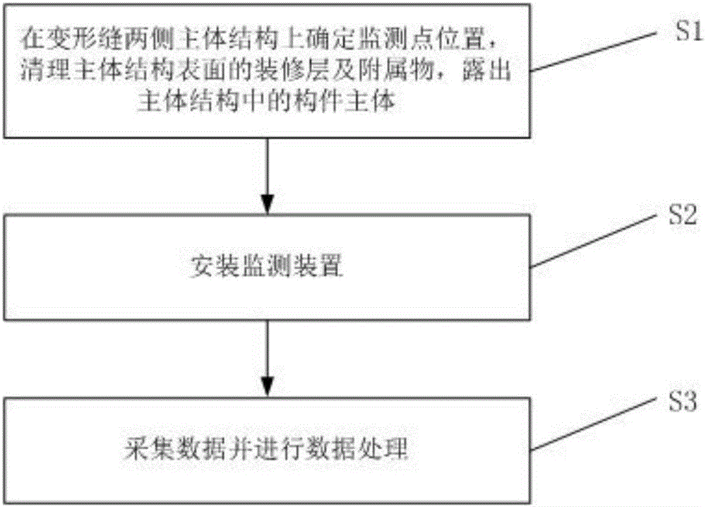
Method for monitoring three-dimensional deformation of main body structures at two sides of deformation joint
A technology of main structure and deformation joints, applied in the direction of measuring devices, instruments, etc., can solve problems such as sensor system error, space utilization influence, monitoring data error, etc., to avoid systematic error, occupy small space, and facilitate installation and maintenance Effect
- Summary
- Abstract
- Description
- Claims
- Application Information
AI Technical Summary
Problems solved by technology
Method used
Image

Examples
Embodiment 1
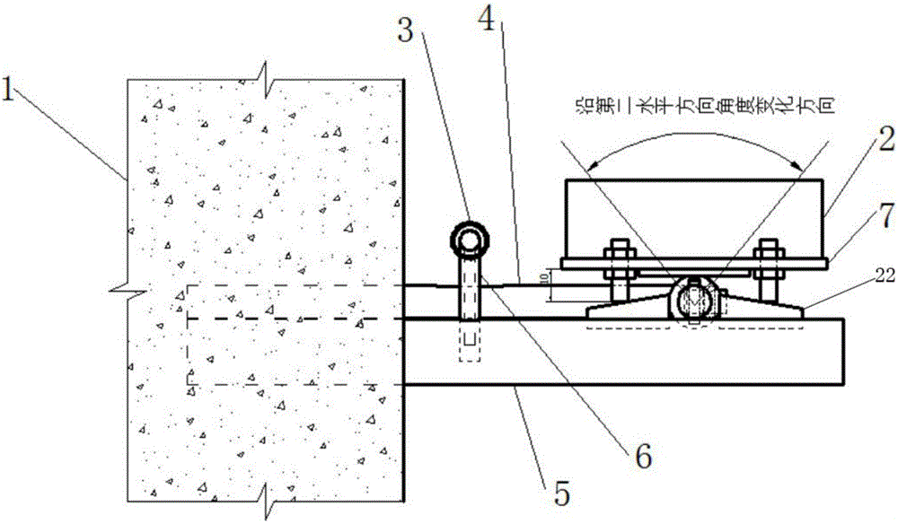
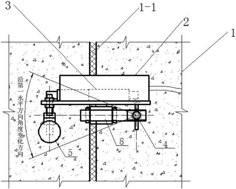
[0080] Measure the horizontal and vertical deformation of the wall, the installation surface is vertical, the first bracket is a "one" shape with a diameter of 10mm; the second bracket is a "one" shape with a diameter of 15mm, the depth of the keyway on the second horizontal bar 3mm, length 25mm, width 10mm; trapezoidal key slope angle ψ=10°, horizontal distance L between the cross-section centers of the first horizontal rod and the second horizontal rod=100mm, connecting shaft axis and bolt-trapezoidal The horizontal distance of the contact point of the key is The corresponding values of a, b, c and α, β, d are shown in Table 1.
[0081] Table 1
[0082]
[0083]
Embodiment 2
[0085]Measure the horizontal and vertical deformation of the wall, the installation surface is vertical, the first bracket is a "one" shape with a diameter of 10mm; the second bracket is a "one" shape with a diameter of 15mm, the depth of the keyway on the second horizontal rod 3mm, length 25mm, width 10mm; trapezoidal key bevel angle ψ=15°, horizontal distance L between the cross-section centers of the first horizontal bar and the second horizontal bar=100mm, connecting shaft axis and bolt-trapezoidal The horizontal distance of the key contact point is The corresponding values of a, b, c and α, β, d are shown in Table 2.
[0086] a(mm)
PUM
 Abstract
Description
Claims
Application Information