
Multi-dimensional, multi-plane, multi-point synchronous soldering device and soldering method

A multi-plane, multi-dimensional technology, applied in tin feeding devices, metal processing equipment, welding equipment, etc., can solve the problems of inability to talk about multi-dimensional synchronization, low efficiency, and inability to use the overall tin printing process of stencils to achieve differences. management, reducing adjustment steps, and improving efficiency

Active Publication Date: 2019-02-22
COMBA TELECOM TECH (GUANGZHOU) CO LTD
View PDF7 Cites 0 Cited by
  • Summary
  • Abstract
  • Description
  • Claims
  • Application Information

AI Technical Summary

Problems solved by technology

Since the metal structure of the base station antenna is a special-shaped structure, the solder joints are distributed in multiple directions, and the number of solder joints is large, it is impossible to use the overall tin printing process of the stencil, and only a tin spotter can be used for tinning
However, the tin spotter itself cannot synchronize multiple points, let alone synchronize multiple dimensions.
[0004] There are some innovations in the industry, that is, the use of a three-dimensional manipulator to drive a single solder dispenser terminal to dispense the required solder. Although it can also meet the quantitative control of the amount of solder dispensed, it is still unable to perform multi-point simultaneous solder dispense operations, only one by one. Sequential tinning of solder joints is extremely inefficient

Method used


Image

  • Multi-dimensional, multi-plane, multi-point synchronous soldering device and soldering method

Examples


Embodiment Construction

[0032] Embodiments of the present invention are described in detail below, examples of which are shown in the drawings, wherein the same or similar reference numerals designate the same or similar elements or elements having the same or similar functions throughout. The embodiments described below by referring to the figures are exemplary only for explaining the present invention and should not be construed as limiting the present invention.

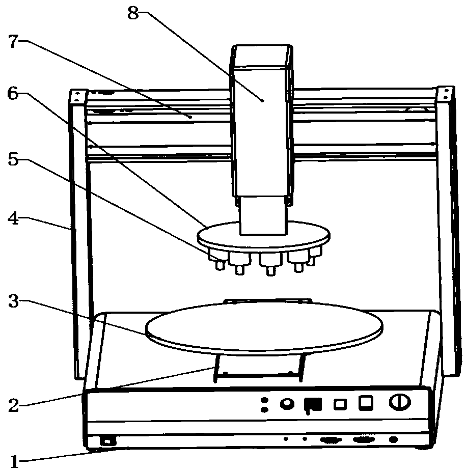
[0033] figure 1 It shows the multi-dimensional, multi-plane, multi-point synchronous tin spotting device (hereinafter referred to as "tin spotting device") of the present invention, including a tin storage device (not shown, the same below), a machine 1, and a machine set on the machine 1. Working platform 3, forward and backward moving mechanism 2, left and right moving mechanism (not shown), lifting mechanism 8, multi-manifold tin-discharging terminal 5, tin-discharging control module (not shown) and control system (not labeled).

[0...


PUM


Abstract

A multi-dimensional multi-point synchronous tin-dispensing device, which comprises: a machine base (1), a tin storage device, an operation platform (3) which is arranged on the machine base (1) and which is provided with a circumferential rotation mechanism, a front-and-back movement mechanism (2), vertical posts (4) disposed at the left and right sides of the machine base (1), a cross beam (7) which connects top ends of the two vertical posts (4) and which is provided with a left-and-right movement mechanism, a lifting mechanism (8) which is connected to the left-and-right movement mechanism and which is capable of left-and-right movements, a multi-branch tin discharging terminal (5) which is connected to the other end of the lifting mechanism (8) and which is connected to the tin storage device, a tin discharging control module which is electrically connected to the multi-branch tin discharging terminal (5) and which controls the multi-branch tin discharging terminal (5) to discharge tin synchronously, and a control system. The present invention also relates to a tin dispensing method to be implemented by the tin-dispensing device. By means of a multiple axial movement system, the positioning of a workpiece and a plurality of tin discharging nozzles of the multi-branch tin discharging terminal (5) may be achieved; by using the tin discharging control module to control the multi-branch tin discharging terminal (5) to discharge tin synchronously, multi-dimensional multi-point synchronous welding may be achieved, which improves welding efficiency.

Description

technical field [0001] The invention relates to the field of soldering technology, in particular to related technologies related to soldering processing in communication devices, and in particular to a multi-dimensional, multi-plane, multi-point synchronous tin spotting device and a tin spotting method. Background technique [0002] In the field of mobile communication technology, the core components of base station antennas are mainly welded by metal structural parts (radiation units) and different components. For each combination form, the details of the welding process are very different. The level of control of the amount of tin used in the welding parameters determines the level of welding yield. In tin brazing, 80% of quality problems occur in the tin control process. Among the problems that are prone to occur in tin control, the following two phenomena are particularly prominent: uneven dosage and positional deviation of tin control. [0003] Solder control, the com...

Claims


Application Information

Patent Timeline
Patent Type & Authority Patents(China)
IPC IPC(8): B23K3/06
CPCB23K3/06
Inventor 吕晓胜郭林波刘峰王文长杨志勇黄武
Owner COMBA TELECOM TECH (GUANGZHOU) CO LTD
Learn More