Electric beating knife cylinder and electric main shaft including electric beating knife cylinder

A cutting tool cylinder, electric technology, applied in the field of electric spindle, can solve the problem of increasing energy consumption

Active Publication Date: 2016-12-07
BEIJING CTB SERVO CO LTD
View PDF10 Cites 5 Cited by
  • Summary
  • Abstract
  • Description
  • Claims
  • Application Information

AI Technical Summary

Problems solved by technology

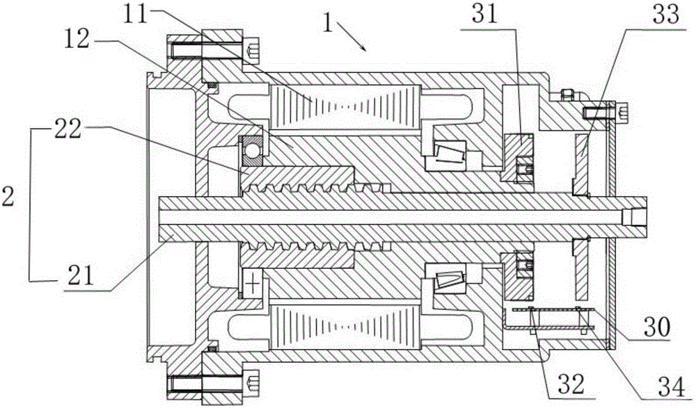
[0004] In order to solve the above-mentioned problems in the prior art, that is, to solve the problem that the existing knife punching cylinder must be equipped with a hydraulic station or an air pump to increase energy consumption, the present invention provides an electric knife punching cylinder, which includes a drive A motor and a...

Method used


Image

  • Electric beating knife cylinder and electric main shaft including electric beating knife cylinder

Examples


Embodiment Construction

[0016] Preferred embodiments of the present invention are described below with reference to the accompanying drawings. Those skilled in the art should understand that these embodiments are only used to explain the technical principles of the present invention, and are not intended to limit the protection scope of the present invention. For example, although various components in the drawings are drawn in a specific scale, such a proportional relationship is only exemplary, and those skilled in the art can make adjustments as needed so as to adapt to specific applications.

[0017] It should be noted that, in the description of the present invention, the terms "center", "upper", "lower", "left", "right", "vertical", "horizontal", "inner", "outer" etc. The indicated orientation or positional relationship is based on the orientation or positional relationship shown in the drawings, and is only for the convenience of describing the present invention and simplifying the description...


PUM


Abstract

The invention belongs to the technical field of electric main shafts, and in particular, relates to an electric beating knife cylinder. The invention aims to solve the problem of increment of the energy consumption due to necessary preparation of a hydraulic station or air pump for a traditional beating knife cylinder. For the purpose, the electric beating knife cylinder, provided by the invention, comprises a driving motor, and a transmission mechanism arranged in the driving motor; the driving motor includes a stator and a rotor; the transmission mechanism includes a lead screw, and a lead screw nut engaged with a lead screw thread; and the lead screw nut is fixedly mounted on the rotor, and can drive axial movement of the lead screw along with rotation of the rotor. The electric beating knife cylinder drives axial movement of the lead screw through synchronous rotation of the rotor and the lead screw nut, replaces traditional hydraulic and pneumatic beating knife cylinders, and realizes the purpose of saving of energy consumption.

Description

technical field [0001] The invention belongs to the technical field of electric spindles, and in particular relates to an electric knife punching cylinder. Background technique [0002] The tool punching cylinder is mainly used for tool punching of the main shaft in the automatic or semi-automatic tool exchange mechanism of machining center machine tools and CNC milling machines, and can also be used as a clamping device for fixtures and other mechanisms. With the continuous development of technology, a new technology that integrates the machine tool spindle and the spindle motor has emerged in the field of CNC machine tools, that is, the electric spindle. At present, with the rapid development and improvement of electric drive technology (frequency conversion speed regulation technology, motor vector control technology, etc.), the mechanical structure of the main drive system of high-speed CNC machine tools has been greatly simplified, basically canceling the pulley drive a...

Claims


Application Information

Patent Timeline
IPC IPC(8): B23Q3/12B23B19/02
Inventor 项久鹏高少静
Owner BEIJING CTB SERVO CO LTD
Why Eureka
Try Eureka