Connecting structure between bridge abutment and road bed for solving problem of vehicle bump at bridge head

A technology for connecting structures and bridge head jumping, applied in bridges, bridge parts, bridge construction, etc., can solve the problems of different settlement times between subgrade and abutment, large filling height, transverse cracks, etc., to reduce road bridge head jumping Problems, settlement difference reduction, and the effect of increasing the service life

Active Publication Date: 2016-12-07
GUILIN UNIVERSITY OF TECHNOLOGY
View PDF7 Cites 3 Cited by
  • Summary
  • Abstract
  • Description
  • Claims
  • Application Information

AI Technical Summary

Problems solved by technology

From the perspective of engineering practice, when using abutment slabs, differential settlement and transverse cracks are likely to occur on the road surface at the junction of the end of the slab and the subgrade, and the problem of "secondary vehicle jumping" is likely to occur; when other single foundation reinforcement treatment methods are used , the filling height is too large, or the settlement time of the subgrade and the abutment is different, so the problem of uneven settlement between the abutment and the abutment cannot be well solved

Method used


Image

  • Connecting structure between bridge abutment and road bed for solving problem of vehicle bump at bridge head

Examples


Embodiment

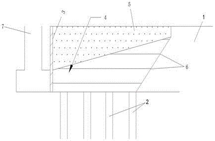
[0015] A connection structure between the bridge abutment and the subgrade used to deal with the problem of vehicle jumping at the bridge head, such as figure 1 As shown, the connection structure is located between the abutment 7 and the original subgrade 1; the connection structure includes CFG pile 2, filling structure 4, cement-soil grouting treatment area 5 and geonet 6; CFG pile 2 is located at the bottom layer, and it is effective The original subgrade 1 is reinforced to reduce the settlement of the original subgrade 1; the filling structure 4 is located on the CFG pile 2, and the filling structure 4 is separated by a geonet 6 and filled with fillers in parallel layers, and each layer of geonet 6 is connected with The fillers of each layer of the filling structure 4 are locked together to form a stable plane, which is used to effectively reduce and control the deformation of the connection structure, and each layer of the filling structure 4 is compacted after filling, wh...


PUM


Abstract

The invention discloses a connecting structure between a bridge abutment and a road bed for solving the problem of vehicle bump at a bridge head. The connecting structure is positioned between the bridge abutment and the original road bed and comprises cement flyash gravel (CFG) piles, a soil filling structure, a cemented soil grouting treatment zone and geonets, wherein the CFG piles are positioned at the bottommost layer, effectively reinforce the original road bed and are used for reducing the settlement of the original road bed; the soil filling structure is positioned above the CFG piles, separated by the geonets, layered in parallel and filled with filler, each layer of geonet is locked together with each layer of filler of the soil filling structure to form a stable plane, the stable plane is used for effectively reducing and controlling the deformation of the connecting structure, and the layers of the soil filling structure are compacted after being filled so as to reduce the settlement of the connecting structure; and the cemented soil grouting treatment zone is positioned at the upper part of the soil filling structure and presents a wedge shape, one end of the cemented soil grouting treatment zone is connected with the back of bridges and culverts behind the bridge abutment, and the other end of the cemented soil grouting treatment zone is connected with the original road bed. The connecting structure disclosed by the invention prolongs the service life of a road surface, reduces the maintenance cost and improves the degrees of driving safety and comfort of a vehicle.

Description

technical field [0001] The invention belongs to the technical field of road and bridge transition section processing, and in particular relates to a connection structure between an abutment and a roadbed for solving the problem of vehicle jumping at a bridge head. Background technique [0002] At present, to solve the problem of vehicle jumping at the bridge head at home and abroad, abutment slabs are often installed in the transition section of roads and bridges, or foundation reinforcement treatment is carried out, such as compacted sand piles, CFG piles, and pipe piles. From the perspective of engineering practice, when using abutment slabs, differential settlement and transverse cracks are likely to occur on the road surface at the junction of the end of the slab and the subgrade, and the problem of "secondary vehicle jumping" is likely to occur; when other single foundation reinforcement treatment methods are used , the filling height is too large, or the settlement tim...

Claims


Application Information

Patent Timeline
Patent Type & Authority Applications(China)
IPC IPC(8): E01D19/00E01D21/00
CPCE01D19/00E01D21/00
Inventor 肖桂元李子农陈学军叶子明李知翰白汉营
Owner GUILIN UNIVERSITY OF TECHNOLOGY
Why Eureka
Try Eureka