
Explosion-proof shock-proof protecting system of cable-girder anchorage zone and manufacturing method of explosion-proof shock-proof protecting system

A protection system and anti-shock technology, applied to bridges, bridge parts, bridge construction, etc., to achieve the effects of avoiding direct collisions, good ductility, and high protection strength

Inactive Publication Date: 2016-12-07
ZHONGBEI UNIV
View PDF7 Cites 6 Cited by
  • Summary
  • Abstract
  • Description
  • Claims
  • Application Information

AI Technical Summary

Problems solved by technology

[0004] Aiming at the deficiencies in the design of existing bridge structures in terms of explosion-proof and shock-proof, the technical problem to be solved by the present invention is to provide a protection system for the cable-girder anchorage area of ​​a large-span cable-girder bridge structure that can actively defend against explosion shocks and the protection system for this protection system. Production Method

Method used


Image

  • Explosion-proof shock-proof protecting system of cable-girder anchorage zone and manufacturing method of explosion-proof shock-proof protecting system
  • Explosion-proof shock-proof protecting system of cable-girder anchorage zone and manufacturing method of explosion-proof shock-proof protecting system
  • Explosion-proof shock-proof protecting system of cable-girder anchorage zone and manufacturing method of explosion-proof shock-proof protecting system

Examples


Embodiment 1

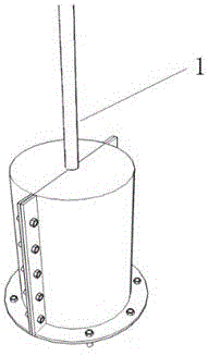
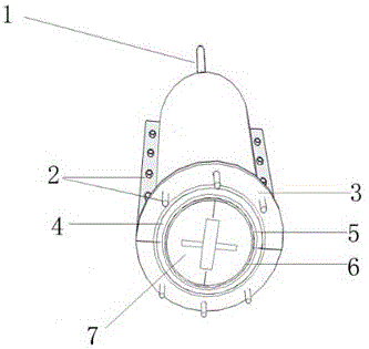
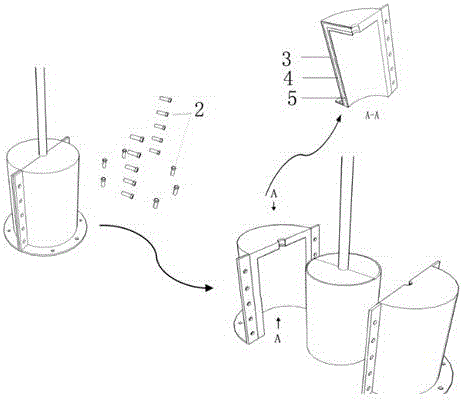
[0043] Such as Figure 1-Figure 5 As shown, an anti-explosion and anti-shock protection system for the anchorage area of ​​a cable beam includes an α-type hemihydrate plaster mold 7, a PTFE membrane material layer 6, an inner steel plate 5, a foamed aluminum layer 4, and an outer steel plate 3. The α-type hemihydrate The gypsum mold 7 is wrapped outside the cable beam anchorage area 1, the PTFE membrane material layer 6 is wrapped around the outside of the α-type hemihydrate plaster mold 7 and the PTFE membrane material layer 6 is at least three layers, and the PTFE membrane material layer 6 is outside The inner steel plate 5, the foamed aluminum layer 4, and the outer steel plate 3 are set sequentially. On the outer side and the bottom of the outer steel plate 3, there are a plurality of high-strength bolts 2 connection holes for connecting with the bridge deck of the cable beam anchorage area 1.

[0044] The α-type hemihydrate gypsum mold 7 is composed of two symmetrical sem...

Embodiment 2

[0064] Such as Figure 1-Figure 5 As shown, an anti-explosion and anti-shock protection system for the anchorage area of ​​a cable beam includes an α-type hemihydrate plaster mold 7, a PTFE membrane material layer 6, an inner steel plate 5, a foamed aluminum layer 4, and an outer steel plate 3. The α-type hemihydrate The gypsum mold 7 is wrapped outside the cable beam anchorage area 1, the PTFE membrane material layer 6 is wrapped around the outside of the α-type hemihydrate plaster mold 7 and the PTFE membrane material layer 6 is at least three layers, and the PTFE membrane material layer 6 is outside The inner steel plate 5, the foamed aluminum layer 4, and the outer steel plate 3 are set sequentially. On the outer side and the bottom of the outer steel plate 3, there are a plurality of high-strength bolts 2 connection holes for connecting with the bridge deck of the cable beam anchorage area 1.

[0065] The α-type hemihydrate gypsum mold 7 is composed of two symmetrical sem...

Embodiment 3

[0085] Such as Figure 1-Figure 5 As shown, an anti-explosion and anti-shock protection system for the anchorage area of ​​a cable beam includes an α-type hemihydrate plaster mold 7, a PTFE membrane material layer 6, an inner steel plate 5, a foamed aluminum layer 4, and an outer steel plate 3. The α-type hemihydrate The gypsum mold 7 is wrapped outside the cable beam anchorage area 1, the PTFE membrane material layer 6 is wrapped around the outside of the α-type hemihydrate plaster mold 7 and the PTFE membrane material layer 6 is at least three layers, and the PTFE membrane material layer 6 is outside The inner steel plate 5, the foamed aluminum layer 4, and the outer steel plate 3 are set sequentially. On the outer side and the bottom of the outer steel plate 3, there are a plurality of high-strength bolts 2 connection holes for connecting with the bridge deck of the cable beam anchorage area 1.

[0086]The α-type hemihydrate gypsum mold 7 is composed of two symmetrical semi...


PUM

PropertyMeasurementUnit
Apertureaaaaaaaaaa
Thicknessaaaaaaaaaa
Apertureaaaaaaaaaa

Abstract

The invention relates to an explosion-proof shock-proof protecting system of a cable-girder anchorage zone and a manufacturing method of the explosion-proof shock-proof protecting system, belongs to the technical fields of highway, railway and municipal engineering traffics and bridge engineering protection, and aims to provide a protecting system of the cable-girder anchorage zone, which can actively defend explosion shock, of a wide-span cable beam bridge structure, and the manufacturing method of the protecting system. The protecting system is characterized in that an alpha type semi-hydrated gypsum mold wraps the outer part of the cable-girder anchorage zone; at least three PTFE film material layers wind and wrap the outer side of the alpha type semi-hydrated gypsum mold; an inner steel plate, a foam aluminum layer and an outer steel plate are sequentially arranged on the outer part of the PTFE film material layer in a sleeving manner; sand blasting is firstly performed on the cable-girder anchorage zone for rust cleaning before the alpha type semi-hydrated gypsum mold is wrapped; after being harden and demouded, the alpha type semi-hydrated gypsum mold needs to be dried and roasted; the cable beam anchoring region is wrapped once again; and then the PTFE film material layers, the inner steel plate, the foam aluminum layer and the outer steel plate are sequentially arranged on the outer part of the alpha type semi-hydrated gypsum mold to form the protecting system. The explosion-proof shock-proof protecting system and the manufacturing method thereof disclosed by the invention are applied to the traffic and the bridge engineering protection.

Description

technical field [0001] An anti-explosion and anti-shock protection system for a cable-beam anchorage area and a manufacturing method thereof, which belong to the technical field of road and railway municipal engineering transportation and bridge engineering protection, and specifically relate to long-span cable-beam bridge structures such as cable-stayed bridges, suspension bridges, and suspension rod arch bridges. The technical field of anti-explosion and anti-shock in the anchorage area of ​​cable beams. Background technique [0002] Cable-beam anchorage structures are widely used in long-span bridge structures such as cable-stayed bridges, suspension bridges, and suspension rod arch bridges. During the operation of bridge structures in this area, due to the lack of professional protective design measures, vehicles transporting flammable and explosive dangerous goods, terrorists, etc. Risks such as deliberate attack and damage, loss of control during driving, etc. will cau...

Claims


Application Information

Patent Timeline
IPC IPC(8): E01D19/14E01D19/00E01D21/00
CPCE01D19/00E01D19/14E01D21/00
Inventor 耿少波刘亚玲薛建英王万月郑亮郭宏陈淑萍吴增煜
Owner ZHONGBEI UNIV
Learn More