Big self-supporting combined steel formwork and firewall construction method thereof

A steel formwork, self-supporting technology, applied in formwork/formwork/work frame, connection parts of formwork/formwork/work frame, on-site preparation of building components, etc. Problems such as construction and template bulging are easy to achieve, achieving the effect of easy assembly and operation, fast construction speed and short construction period

Active Publication Date: 2016-12-07
SHANDONG ELECTRIC POWER TRANSMISSION & SUBSTATION ENG CO
View PDF6 Cites 9 Cited by
  • Summary
  • Abstract
  • Description
  • Claims
  • Application Information

AI Technical Summary

Problems solved by technology

At present, the construction of firewalls is mostly carried out by overlapping brackets, which takes a long time and is inefficient.
[0004] Chinese patent CN103669831A discloses a combined steel form for a cast-in-place wall of a substation and a construction method thereof, and specifically relates to a combined steel form for a cast-in-place wall of a substation and a construction method thereof. At least one steel standard face on the inner and outer walls of the body and at least one steel non-standard face set on the end face of the cast-in-place wall, the standard faces are composed of additional layers, standard layers, additional layers and standard Layers are staggered from bottom to top, and the invention overcomes the quality problems caused by traditional construction methods, such as easy swelling of formwork and leakage of grout at joints; the steel mold can only be used at a lower height, and cannot adapt to construction at a higher position , even if several steel molds are built by means of multi-layer accumulation and bolted connection, the stability of the structure cannot be guaranteed, and the risk of collapse is prone to occur
From this embodiment, it is not difficult to find the situation that there is leakage of top material

Method used


Image

  • Big self-supporting combined steel formwork and firewall construction method thereof
  • Big self-supporting combined steel formwork and firewall construction method thereof
  • Big self-supporting combined steel formwork and firewall construction method thereof

Examples


Embodiment Construction

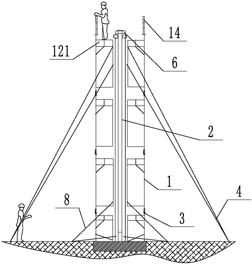
[0057] Such as Figure 1 to Figure 6 As shown, the present invention provides a self-supporting combined large steel formwork, including a supporting door bracket 1, a positive and negative buckle adjustment screw 3 connected between the door brackets 1 and the door Formwork connector 5 for connecting the type support 1 and the building formwork 2.

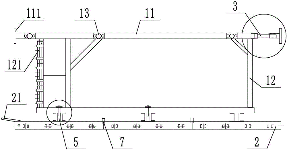
[0058] Such as figure 2 As shown, the door-type bracket 1 includes at least two door-shaped frame structures composed of two first supports 11 arranged vertically and a plurality of second supports 12 arranged vertically between the first supports 11, The door-shaped frame structures are connected by reinforcing braces 13, such as figure 2 As shown, the reinforcing brace 13 is provided with a plate with holes, which is connected and fixed with the first support 11 by bolts, and an operating platform 121 is provided on the second support 12 at the top of each section of the door bracket 1.

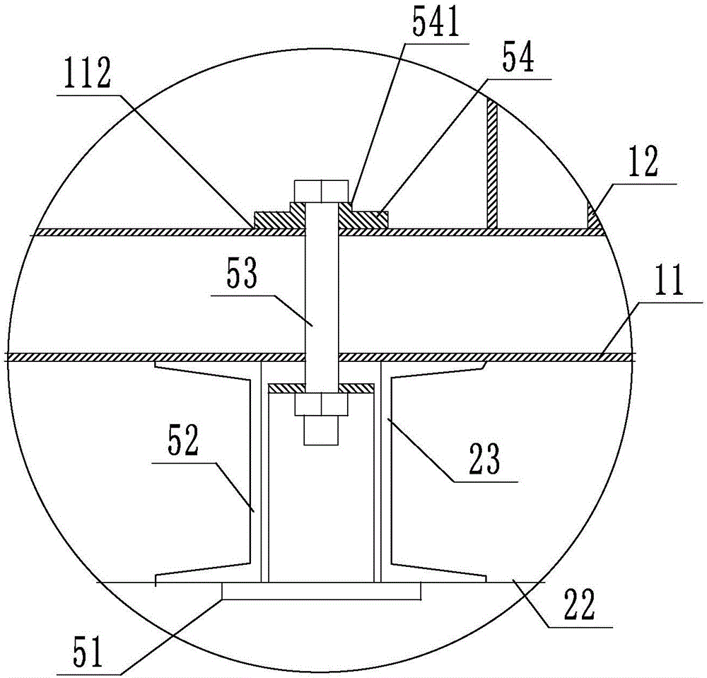
[0059] Such as Figure 5 with Image 6 As ...


PUM


Abstract

The invention provides a big self-supporting combined steel formwork and relates to the technical field of building formworks. The big self-supporting combined steel formwork comprises a portal supporting frame, a right-hand thread adjustment lead screw, a left-hand thread adjustment lead screw and formwork connectors. The portal supporting frame comprises portal frame structures composed of first supports and second supports, and the portal frame structures are connected through reinforcing supports. An operation platform is arranged on the second support at the topmost end of each section of the portal supporting frame. The big self-supporting combined steel formwork further comprises double-hook connectors and a firewall coping mold, wherein adjacent building formworks are connected through the double-hook connectors, and the firewall coping mold is mounted at the top of the building formwork. The invention further provides a construction method for constructing a bare concrete firewall through the big self-supporting combined steel formwork. By the adoption of the construction method, the problems of inclining, slab staggering, mortar leakage and the like caused after building formworks are assembled in the prior art can be solved; the construction speed is high, and mounting is convenient; and operation for field assembly of the steel formwork is easy, the degree of mechanization is high, and the construction cycle is short.

Description

Technical field [0001] The invention relates to the technical field of building templates, in particular to a self-supporting combined large steel template and a construction method for using the template to construct fair-faced concrete firewalls. Background technique [0002] In actual use, building templates are generally assembled into various shapes according to construction needs. At present, in the assembly process, most adjacent two templates are directly connected by ordinary steel bolts, and then connected through several legs. Carry out reinforcement support. Although this splicing method can effectively improve the efficiency of disassembly and assembly to a certain extent, the direct use of ordinary bolting not only requires frequent lifting of the formwork during the assembly process, but also the integrity of the connection between the building formwork after assembly is not good, especially for the upper and lower parts. The verticality after the assembly of the ...

Claims


Application Information

Patent Timeline
Patent Type & Authority Applications(China)
IPC IPC(8): E04G11/08E04G17/14E04G17/04
CPCE04G11/08E04G11/085E04G17/04E04G17/047E04G17/14
Inventor 吕念胡俊鹏邵中华韩荣国李继征孙朝晖马祖健马福雷单波韩义成
Owner SHANDONG ELECTRIC POWER TRANSMISSION & SUBSTATION ENG CO
Why Eureka
Try Eureka