
Natural gas hydrate blocking monitoring device and method in deepwater gas well test

A monitoring device and hydrate technology, which are used in earth-moving drilling, wellbore/well components, etc., can solve problems such as hydrate clogging, hydrate clogging, hydrate clogging, etc. question

Active Publication Date: 2016-12-07
CHINA UNIV OF PETROLEUM (EAST CHINA)
View PDF8 Cites 26 Cited by
  • Summary
  • Abstract
  • Description
  • Claims
  • Application Information

AI Technical Summary

Problems solved by technology

Patent CN104088623A determines the hydrate formation area in the test column based on the hydrate formation phase equilibrium theory, and provides hydrate prevention methods based on this, but this patent cannot be used to monitor and analyze when and where the hydrate will be formed in the test column. Hydrate plugging, and the severity with which it occurs
Patent CN104343416A discloses a deep-water gas well testing system and testing method. It proposes to determine the hydrate forming area in the test string based on the hydrate forming phase equilibrium theory, and then adopts the downhole throttling method to prevent and control hydrate. This patent cannot be used for monitoring And analyze when and where hydrate blockage will occur in the test column, and the severity of hydrate blockage
Patent CN104895560A discloses a deep water test wellbore pressure, temperature field simulation and hydrate prediction method. This patent can only judge where in the test wellbore satisfies the temperature and pressure conditions for hydrate formation, and does not involve hydrate formation rate, hydrate deposition Problems such as clogging cannot be used to monitor and analyze when and where hydrate clogging occurs in the test string, as well as the severity of clogging

Method used

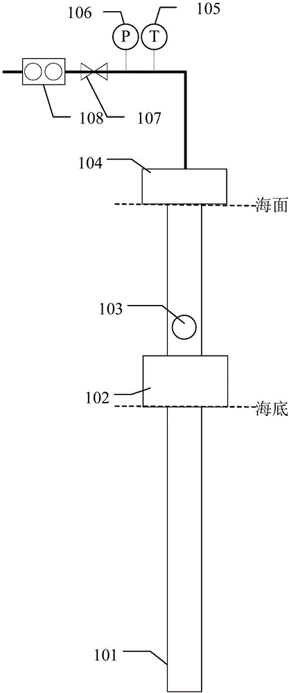
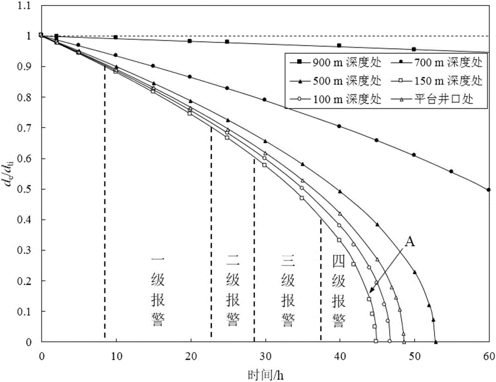

Image

  • Natural gas hydrate blocking monitoring device and method in deepwater gas well test
  • Natural gas hydrate blocking monitoring device and method in deepwater gas well test
  • Natural gas hydrate blocking monitoring device and method in deepwater gas well test

Examples


Embodiment Construction

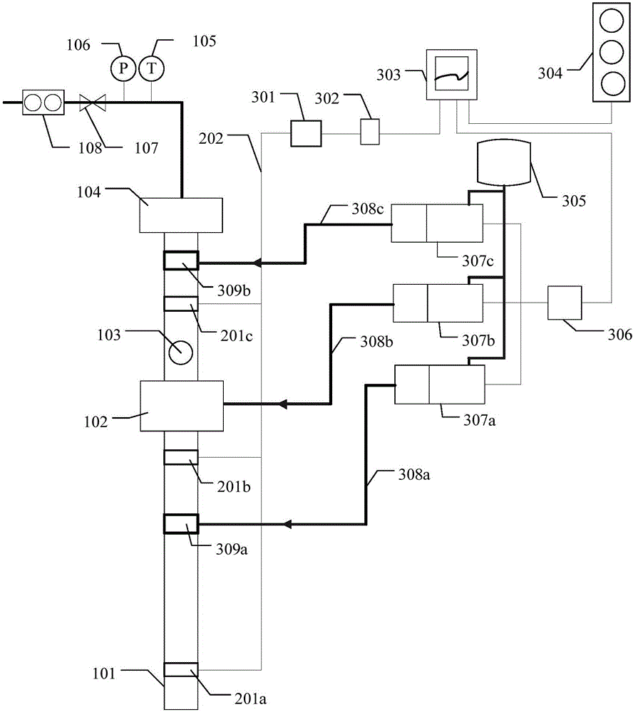
[0014] Such as figure 2 As shown, the gas hydrate plugging monitoring device in deepwater gas well testing includes: downhole data acquisition and transmission system, platform control system and hydrate inhibitor automatic injection system. The downhole data acquisition and transmission system monitors the temperature and pressure data of the fluid in the test string in real time, and transmits the monitored temperature and pressure data to the platform control system; the platform control system monitors the severity of gas hydrate blockage in the test string, the The time required to be completely blocked and the position where complete blockage occurs first are calculated and evaluated, corresponding warning signals are issued, and instructions for injecting hydrate inhibitors are issued according to the blockage of the pipe string; the automatic injection system of hydrate inhibitors is based on the platform control system. The corresponding hydrate inhibitor injection p...


PUM


Abstract

The invention relates to a natural gas hydrate blocking monitoring device in a deepwater gas well test. The natural gas hydrate blocking monitoring device comprises a downhole data collecting and transmitting system, a platform control system and a hydrate inhibitor automatic injection system. The downhole data collecting and transmitting system monitors temperature and pressure data of fluid in a test tubular column in real time and transmits the data to the platform control system. The platform control system calculates and evaluates the natural gas hydrate blocking condition in the test tubular column, sends a corresponding early warning signal, sends an order for injecting a hydrate inhibitor according to the blocking condition of the tubular column, starts a corresponding hydrate inhibitor injection pump, and injects the hydrate inhibitor into the test tubular column through a hydrate inhibitor injection pipeline and a hydrate inhibitor injection connector. Through the natural gas hydrate blocking monitoring device, the hydrate blocking position, the hydrate blocking severity degree and time needed by complete blocking in deepwater gas well test work can be calculated, and setting of hydrate controlling measures can be guided.

Description

technical field [0001] The invention belongs to the field of marine deep-water oil and gas exploration and development, and in particular relates to a monitoring device and method for natural gas hydrate blockage in deep-water gas well testing. Background technique [0002] With the gradual depletion of onshore oil and gas resources, exploration and development activities are gradually shifting to the deepwater field, and the contribution of new oil and gas proven reserves in the deepwater field to the overall new oil and gas proven reserves in the world continues to rise. The report of the 18th National Congress of the Communist Party of China clearly put forward the strategy of building a "marine power" and strengthening the development of offshore oil and gas resources is of great significance to building a marine power. Many technical challenges will be encountered in deepwater oil and gas drilling operations. Among them, the formation of gas hydrates under low temperatu...

Claims


Application Information

Patent Timeline
Patent Type & Authority Applications(China)
IPC IPC(8): E21B49/00
Inventor 王志远赵阳孙宝江关利军张剑波杨彩凤张振楠王雪瑞
Owner CHINA UNIV OF PETROLEUM (EAST CHINA)
Learn More