A fuel injection system component of an aerospace engine and a fuel injection method thereof

A technology of aerospace and fuel injection systems, which is applied to engine components, machines/engines, turbines/propellant fuel delivery systems, etc. It can solve the problems of insufficient power, poor fuel atomization effect, and failure to return oil to achieve strong output power , fully mixed and fully fueled

Active Publication Date: 2017-12-12
成立航空技术(成都)有限公司
View PDF7 Cites 0 Cited by
  • Summary
  • Abstract
  • Description
  • Claims
  • Application Information

AI Technical Summary

Problems solved by technology

Especially the research and development of the engine fuel system of fighter jets is even more difficult. Most of the current fuel injection systems are single or multiple used side by side, and there are not many fuel injection systems in groups.
[0003] The existing fuel injection system only fixes multiple fuel injectors together, cannot return fuel, and cannot control the pressure. During the flight of the aircraft, due to the inertia, the integral structure fixed together will shift during the transportation process. , As a result, the fuel in the pipeline is not uniformly delivered to the injector, the pressure near the fuel pipeline is high, and the pressure far away from the fuel pipeline is low, resulting in uneven injection of the output fuel into the combustion chamber, and the large amount of fuel leads to combustion. Insufficient black smoke, or lack of power due to insufficient oil
At the same time, the air outlet control of the ordinary fuel injection system is straight, consistent with the fuel injection direction, and cannot further tear the atomized fuel, so the fuel atomization effect is poor and the air is not mixed uniformly, resulting in insufficient fuel combustion and affecting Power output of fuel injection system

Method used


Image

  • A fuel injection system component of an aerospace engine and a fuel injection method thereof
  • A fuel injection system component of an aerospace engine and a fuel injection method thereof
  • A fuel injection system component of an aerospace engine and a fuel injection method thereof

Examples


Embodiment Construction

[0024] In order to further understand the content of the invention, characteristics and effects of the present invention, the following examples are described in detail as follows:

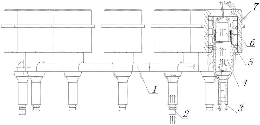
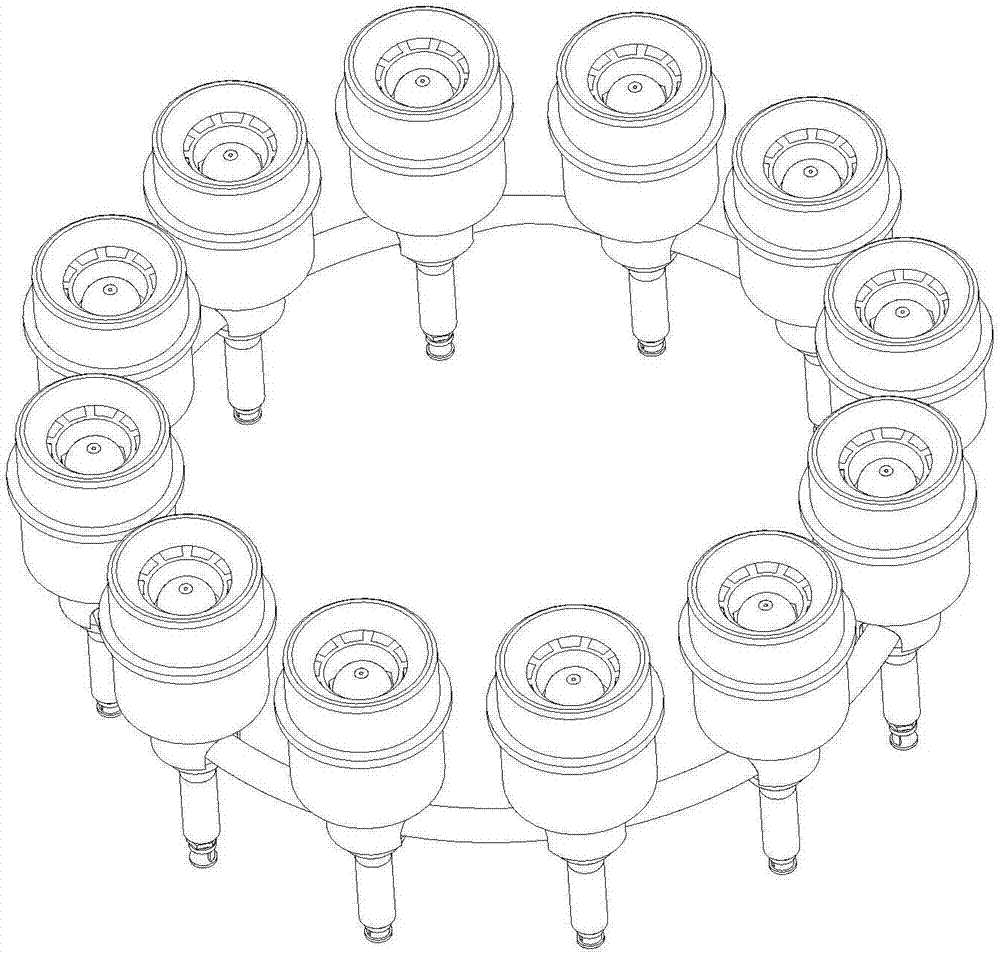
[0025] See figure 1 and figure 2 , the present invention comprises a plurality of bottle-shaped main pipe bodies 4 and multi-section arc-shaped pipe bodies 1, and each bottle-shaped main pipe body 4 communicates with each other through the arc-shaped pipe bodies 1 to form a ring-shaped whole; the upper end of the bottle-shaped main pipe body 4 is installed There is a fuel injection nozzle 5, and an air intake guide vane fan 6 is arranged outside the fuel injection nozzle 5, and an outer cover body 7 is arranged outside the air intake guide vane fan 6; the lower ends of each bottle-shaped main body 4 are respectively installed with pressure relief valves at intervals. Oil nozzle 3 and oil inlet nozzle 2.

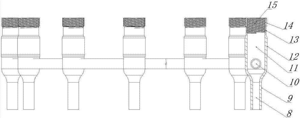
[0026] See image 3 , the bottle-shaped main body 4 is an upside-down, wine bottle-shaped...


PUM


Abstract

The invention belongs to the technical field of aerospace engine fuel injection systems, and in particular relates to an aerospace engine fuel injection system assembly, and also relates to a fuel injection method using the above-mentioned system assembly. The present invention comprises a plurality of bottle-shaped main pipe bodies and multi-section arc-shaped pipe bodies, and the bottle-shaped main pipe bodies communicate with each other through the arc-shaped pipe bodies to form a ring-shaped whole; the upper end of the bottle-shaped main pipe body is equipped with a fuel injection nozzle, An air intake guide vane fan is arranged outside the fuel injection nozzle, and an outer cover is arranged outside the air intake guide vane fan; pressure relief oil return nozzles and oil inlet nozzles are respectively installed at intervals at the lower ends of each bottle-shaped main body. The present invention adopts the pressure relief oil return nozzle to control the oil pressure of each fuel injection nozzle, so that the fuel is evenly delivered to each fuel injection nozzle; at the same time, the spiral guide vane fan is used, and the air passes through the spiral guide vane fan to form a whirlwind, and the whirlwind further transfers the fuel The tearing atomization makes the fuel and air mix more fully, the fuel in the combustion chamber is more sufficient, and the output power is stronger.

Description

technical field [0001] The invention belongs to the technical field of aerospace engine fuel injection systems, and in particular relates to an aerospace engine fuel injection system assembly, and also relates to a fuel injection method using the above-mentioned system assembly. Background technique [0002] At present, in the field of aerospace, many engine fuel injection systems are imported, and domestic production is very small, and they are all in a low-end position. Especially the research and development of the engine fuel system of fighter jets is even more difficult. Most of the existing fuel injection systems are single or multiple used side by side, and there are not many fuel injection systems in groups. [0003] The existing fuel injection system only fixes multiple fuel injectors together, cannot return fuel, and cannot control the pressure. During the flight of the aircraft, due to the inertia, the integral structure fixed together will shift during the transp...

Claims


Application Information

Patent Timeline
Patent Type & Authority Patents(China)
IPC IPC(8): F02C7/236F02C7/22F02C7/28F02C9/26
Inventor 王鹏陈立郝晓波樊淼海李晓宁
Owner 成立航空技术(成都)有限公司
Why Eureka
Try Eureka