
A pneumatic air flotation rotating device

A rotating device and air bearing technology, which is applied in the direction of air cushion bearings, anti-centrifugal force rotating parts, bearings, etc., to achieve high precision, excellent speed control performance, and friction-free effects

Active Publication Date: 2019-03-19
CHONGQING UNIV
View PDF5 Cites 0 Cited by
  • Summary
  • Abstract
  • Description
  • Claims
  • Application Information

AI Technical Summary

Problems solved by technology

[0005] In view of this, the purpose of the present invention is to provide a pneumatic air-floating rotating device to solve the defects existing in the existing optical fiber winding machine and the rotating mechanism of high-precision industrial CT scanning equipment

Method used


Image

  • A pneumatic air flotation rotating device
  • A pneumatic air flotation rotating device
  • A pneumatic air flotation rotating device

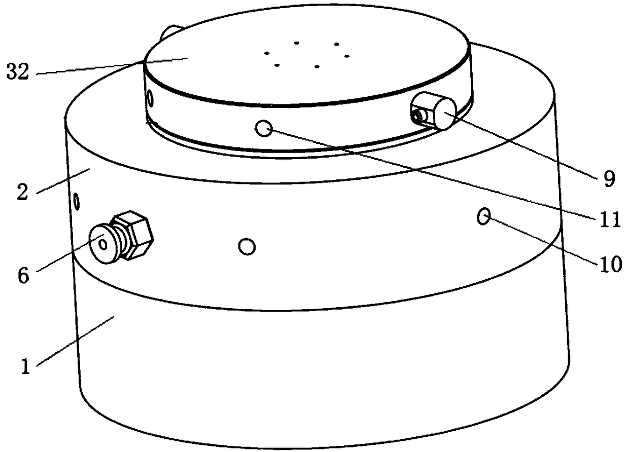
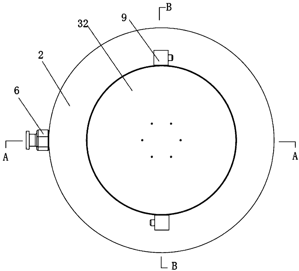
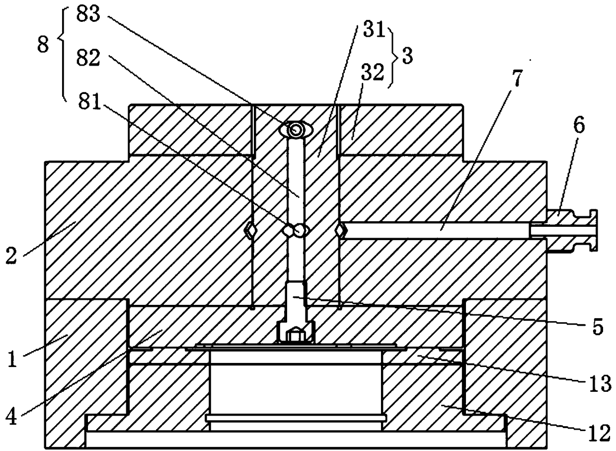
Examples


Embodiment Construction

[0023] The preferred embodiments of the present invention will be described in detail below in conjunction with the accompanying drawings; it should be understood that the preferred embodiments are only for illustrating the present invention, rather than limiting the protection scope of the present invention.

[0024] Such as Figure 1-4 As shown, a pneumatic air bearing rotating device of the present invention includes a rotating body, an air guiding system and a braking system. 4, the shaft sleeve 2 is fixedly installed with the bottom shell seat 1, and the thrust plate 3 with a shaft includes a rotating shaft 31 and a turntable 32 arranged on the rotating shaft 31. The rotating shaft 31 and the turntable 32 are of an integrated structure. The stiffness of the shaft thrust plate; and the rotating shaft 31 is sleeved in the shaft sleeve 2, and at the end far away from the turntable 32, it is detachably fixedly connected with the lower thrust plate 4 through the confinement sc...


PUM


Abstract

The invention discloses a pneumatic air flotation rotating device, and belongs to an optical fiber winding machine technology and the technical field of high-precision industrial computed tomography (CT). The pneumatic air flotation rotating device comprises a rotating body, an air guide system and a brake system; the rotating body mainly consists of a bottom shell base, a shaft sleeve, a thrust plate with a shaft and a lower thrust plate; the air guide system mainly consists of a straight terminal air nozzle, an intake channel, an exhaust channel and a thrust nozzle; and the brake system is arranged at the bottom of the lower thrust plate and in the bottom shell base. The pneumatic air flotation rotating device mainly solves the defect of nonuniform tension in a traditional industrial optical fiber winding machine and high-precision space rotary positioning requirements of detected objects in industrial computed tomography, has such advantages as high precision, constant torque, high disturbance resistance, no friction force, no wear, no need of lubricating oil, better torque performance and no noise, and can fully satisfy the requirements of the industrial optical fiber winding machine and an industrial CT scanning system.

Description

technical field [0001] The invention belongs to the technical fields of optical fiber ring winding machine technology and high-precision industrial computerized tomography, and in particular relates to a pneumatic air-floating rotating device. Background technique [0002] The optical fiber winding machine realizes the winding of the optical fiber through the rotating shaft. Because the optical fiber is relatively thin, the constant torque function of the rotating device in the past optical fiber winding machine does not work well during the winding process, resulting in inconsistent fiber winding tightness. In addition, manual wiring is required. , it will inevitably cause uneven winding, and at the same time, the work intensity is high and the yield is low. [0003] Industrial computerized tomography (ICT) is a non-contact advanced non-destructive testing method. It can display the internal structural relationship and defect status of the detected object in the form of to...

Claims


Application Information

Patent Timeline
Patent Type & Authority Patents(China)
IPC IPC(8): F16C32/06
CPCF16C32/0622F16C2300/22
Inventor 王福全王珏胡传晒
Owner CHONGQING UNIV
Learn More