
LED lamp capable of rising and falling automatically

A technology of LED lamps and automatic lifting, which is applied to the parts of lighting devices, semiconductor devices of light-emitting elements, lighting and heating equipment, etc. It can solve the problem of not having monitoring functions, and being unable to control the height of lamps and the number of lights according to human needs, etc. problem, to achieve the effect of increasing concealment, simple and convenient use, and convenient and simple use

Inactive Publication Date: 2016-12-07
SICHUAN SKSAS HIGH TECH CO LTD
View PDF3 Cites 0 Cited by
  • Summary
  • Abstract
  • Description
  • Claims
  • Application Information

AI Technical Summary

Problems solved by technology

In the existing LED extension lights, it is still impossible to control the height of the lights and the number of lights according to human needs, and the existing extension lights do not have the monitoring function

Method used


Image

  • LED lamp capable of rising and falling automatically

Examples


Embodiment 1

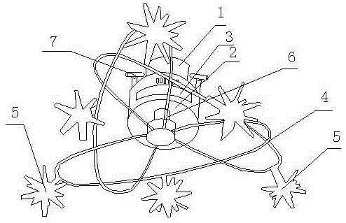
[0020] Such as figure 1 As shown, the present invention includes a fixed seat 2, a control panel 3 and a lifting head 6, the top of the fixed seat 2 is connected to the lamp interface 1, the control panel 3 is arranged inside the fixed seat 2, and the lifting head 6 is connected at the bottom of the fixed seat 2 , the bottom of the lifting head 6 is connected to the installation strip 4, the installation strip 4 is connected to the control panel 3, the installation strip 4 is bent and coiled multiple times to form a plurality of staggered ellipses, and a plurality of LED lights are evenly installed on the installation strip 4, and the LED lights are connected through the lines arranged inside the installation bar 4; the control panel 3 includes a control module, an LED driver module, a WiFi module and an analog-to-digital conversion module, wherein the LED driver module, the WiFi module and the analog-to-digital conversion module are all connected On the control module, a phot...

Embodiment 2

[0023] This embodiment is preferably as follows on the basis of Embodiment 1: the camera 7 can realize 0°-360° rotation. The camera can rotate without dead angle, and the monitoring range is wider.

[0024] Dual cameras 7 are set on the holder 2 . Monitoring is more in place.

[0025] Multiple corners of different sizes are arranged on each LED lamp. The LED lights emit light more evenly.

[0026] A plurality of ventilation holes are also arranged on the side of the fixing seat 2 . Used to quickly dissipate heat inside the mount.

[0027] The model of the WiFi module is MV269. This type of WiFi module is cost-effective, stable in function, and good in heat resistance, which is very suitable for use in the field of extended lights.

[0028] The model of the control module is A1-PWR-0101. This type of control module can fully meet the needs of controlling lights.


PUM


Abstract

The invention discloses an LED lamp capable of rising and falling automatically. The LED lamp comprises a fixed seat, a control panel and a lifting head. A lamp connector is hinged to the top of the fixed seat. The control panel is arranged in the fixed seat. The lifting head is connected to the bottom of the fixed seat. An installation strip is connected to the bottom of the lifting head and connected with the control panel. The installation strip is bent and wound by a plurality of circles. A plurality of LED lamp bodies are installed on the installation strip and connected through circuits arranged in the installation strip. The control panel comprises a control module, an LED driving module, a WiFi module and an analog-digital conversion module. The LED driving module, the WiFi module and the analog-digital conversion module are all connected to the control module. A photosensitive module is further connected to the analog-digital conversion module. A camera is further installed at the top of the fixed seat. According to the LED lamp, through the structure, the number of lighted lamps and the heights of the lamps can be controlled manually in an auxiliary mode according to the needs of a user, and a monitoring function is achieved at the same time.

Description

technical field [0001] The invention relates to the field of LED lamps, in particular to an LED lamp capable of automatic lifting. Background technique [0002] The current world economy is developing rapidly, and the most important way to develop the economy is to develop industry. In the process of industrial production, a lot of energy will be consumed, but the energy reserves in the world today are decreasing day by day, gradually turning into a situation of energy shortage, energy saving and fully automatic It is a hot topic in today's society. On the one hand, people want to minimize the unnecessary power consumption of lights. On the other hand, people hope that lights have certain intelligence and can automatically turn on and off according to actual conditions, thus saving manpower. costs and improve quality of life. In the existing LED extension lights, the height and the number of lights cannot be controlled according to human needs, and the existing extension li...

Claims


Application Information

Patent Timeline
Patent Type & Authority Applications(China)
IPC IPC(8): F21S8/06F21V21/14F21V23/00F21V33/00F21Y115/10
CPCF21S8/06F21V21/14F21V23/003F21V33/0052
Inventor 张彬
Owner SICHUAN SKSAS HIGH TECH CO LTD
Learn More