A gas generating device

A technology of gas generation and gas, applied in combustion chambers, combustion methods, combustion equipment, etc., can solve problems such as uneven gas outlet temperature, long ignition delay time, and shorten ignition delay, so as to improve work ability and work reliability , Solve the effect of short ignition delay time and shorten ignition delay

Active Publication Date: 2019-04-09
BEIJING AEROSPACE PROPULSION INST
View PDF11 Cites 0 Cited by
  • Summary
  • Abstract
  • Description
  • Claims
  • Application Information

AI Technical Summary

Problems solved by technology

[0004] The technical problem to be solved by the present invention is: to overcome the deficiencies of the prior art, provide a gas generating device, solve the problems of long ignition delay time, low ignition reliability and uneven gas outlet temperature, and shorten the ignition delay from the structural design , improve ignition reliability and uniformity of gas outlet temperature

Method used


Image

  • A gas generating device
  • A gas generating device
  • A gas generating device

Examples


Embodiment Construction

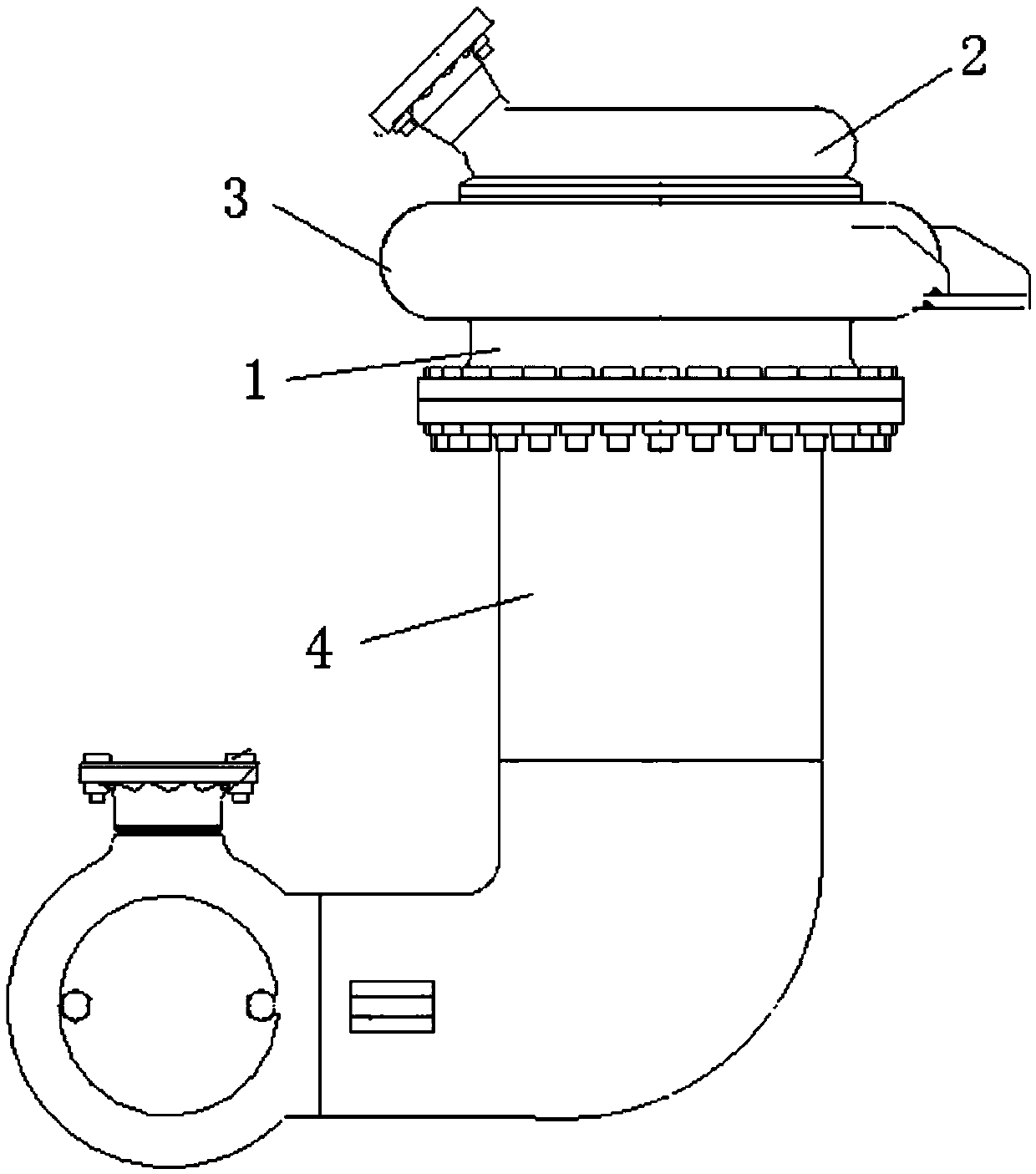
[0017] Such as figure 1 As shown, a gas generating device includes: an injector 1, an oxidant collector 2, a fuel collector 3, and a body 4; wherein, the injector 1, the oxidant collector 2, and the fuel collector 3 are all welded, It is connected with the body through the flange. The oxidant collector 2 and the fuel collector 3 are installed on the injector 1 .

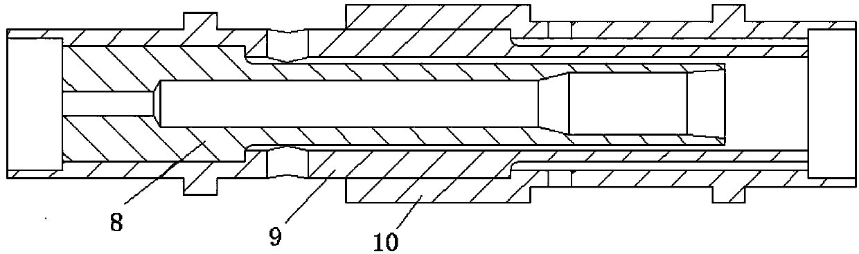
[0018] During the working process, the oxidant and fuel enter the injector 1 through the annular oxidant collector 2 and the fuel collector 3 respectively, and then atomize through the double coaxial nozzle 5 and the coaxial direct-flow nozzle 6 in the injector 1 After combustion, the products of combustion enter the body 4 .

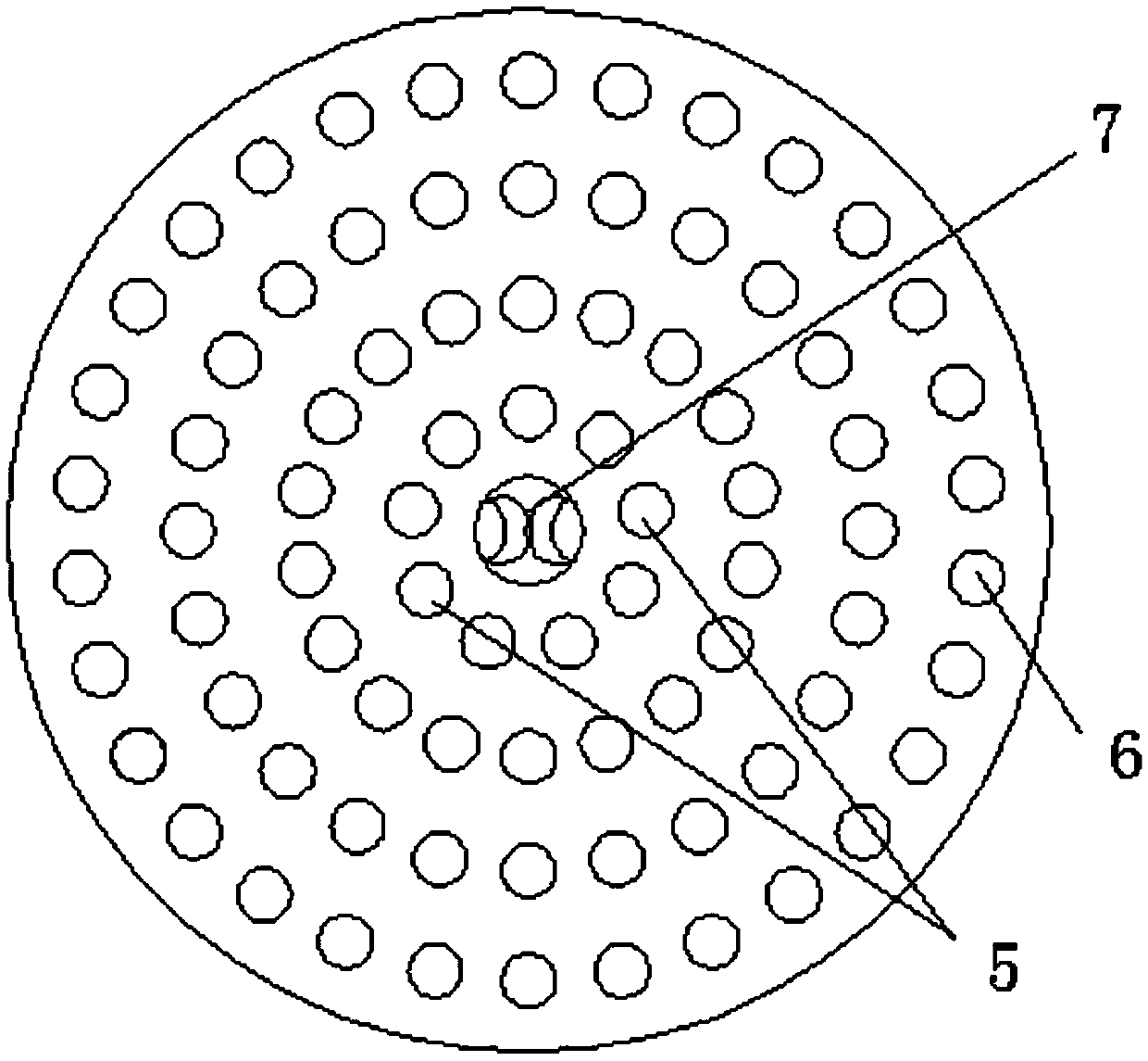
[0019] Injector 1 structure such as figure 2 As shown, it consists of double coaxial nozzles 5, coaxial direct-flow nozzles 6 and flame diffusion tubes 7. Arrange two double-coaxial nozzles 5 near the flame diffusion pipe 7, the angle between the center of the installation hole of the two...


PUM


Abstract

The invention provides a fuel gas generating device. The fuel gas generating device comprises an injector (1), an oxidizing agent collector (2), a fuel collector (3) and a body (4), wherein the oxidizing agent collector (2) and the fuel collector (3) are arranged on the injector (1) which is connected to the body (4); an oxidizing agent and fuel enter the injector (1) respectively through the circular ring-shaped oxidizing agent collector (2) and the fuel collector (3), then are atomized by double coaxial nozzles (5) and coaxial direct-flow type nozzles (6) in the injector (1) and finally are burned; and products generated after burning enter the body (4). The fuel gas generating device solves the problems of long ignition delay time, low ignition reliability and uneven fuel gas outlet temperature, shortens ignition delay and improves ignition reliability and evenness of fuel gas outlet temperature from structural design.

Description

technical field [0001] The invention relates to a gas generating device. Background technique [0002] Gas generators are widely used in aerospace, civil, ignition and combustion technology fields. The injector design of the existing gas generating device is mostly a coaxial direct-flow nozzle and an ignition flame diffusion tube structure, which affects the transfer of ignition flame energy, and its ignition delay time is relatively long, and its ignition reliability is low. However, the single cylindrical segment structure downstream of the combustion chamber prevents the combustion products from being fully mixed and directly enters the downstream, resulting in poor temperature uniformity and affecting the normal operation of downstream components. [0003] The nozzles in the existing gas generating device generally adopt several nozzles of the same structure, such as the axial direct-flow nozzle, and the combustion chamber is generally a cylindrical section with a certa...

Claims


Application Information

Patent Timeline
Patent Type & Authority Patents(China)
IPC IPC(8): F23R3/28
CPCF23R3/286
Inventor 王仙田原丁兆波许晓勇潘刚张晋博李丹琳郑孟伟刘中祥孙纪国
Owner BEIJING AEROSPACE PROPULSION INST
Why Eureka
Try Eureka