Pnumatically actuated bi-propellant valve (PABV) system for a throttling vortex engine

Inactive Publication Date: 2012-05-31
UNITED STATES OF AMERICA THE AS REPRESENTED BY THE SEC OF THE ARMY
View PDF7 Cites 0 Cited by
  • Summary
  • Abstract
  • Description
  • Claims
  • Application Information

AI Technical Summary

Benefits of technology

[0010]PABV is intended to enhance the flexibility of vortex engines by allowing efficient throttling of the engine while helping to mitigate propellant ignition delay. As has been mentioned, excess heat build-up in the manifolds can jeopardize the integrity of unburned propellant. The present invention is designed to decouple the

Problems solved by technology

As has been mentioned, excess heat build-up in the manif

Method used


Image

  • Pnumatically actuated bi-propellant valve (PABV) system for a throttling vortex engine
  • Pnumatically actuated bi-propellant valve (PABV) system for a throttling vortex engine
  • Pnumatically actuated bi-propellant valve (PABV) system for a throttling vortex engine

Examples


Example

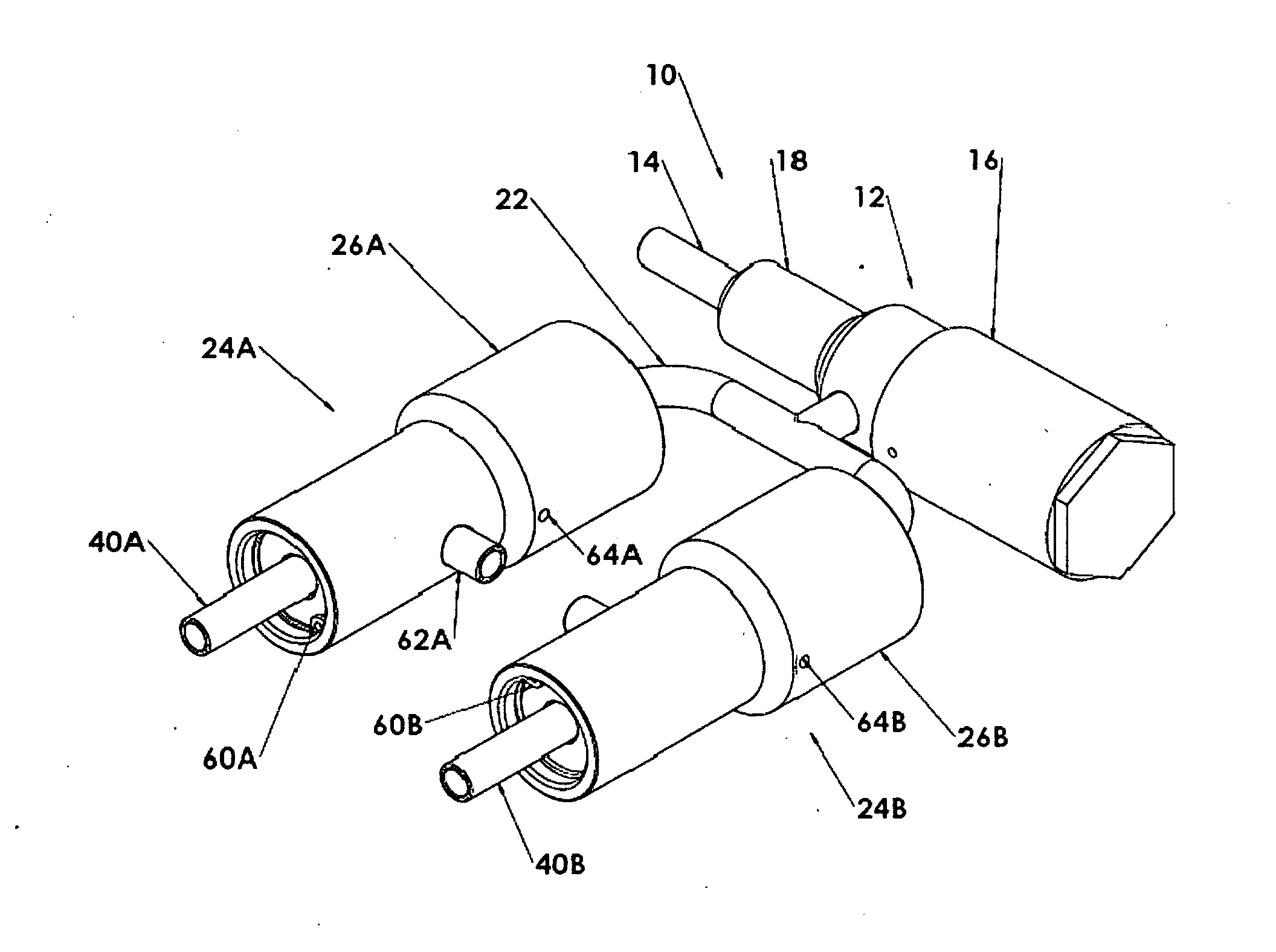
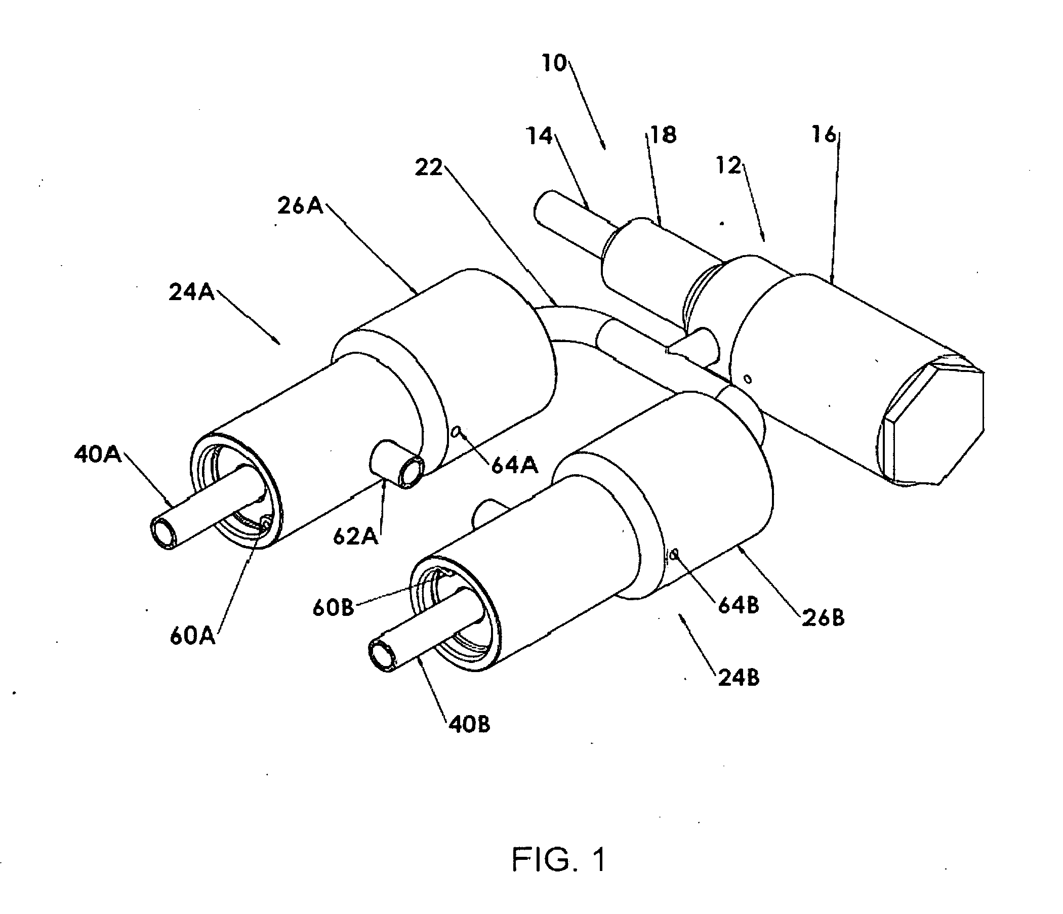
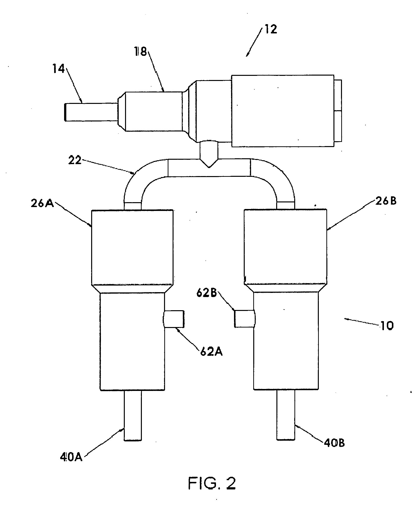
[0017]With reference to FIG. 1 and FIG. 2, the pneumatically actuated bi-propellant valve (PABV) system 10 of the present invention has a pilot valve assembly 12, a first valve mechanism 24A and a second valve mechanism 24B. The first valve mechanism is activated by the pilot valve assembly 12 to dispense fuel to the injector valve housing (not shown) of a throttling vortex engine system.

[0018]When the pilot valve assembly 12 activates the first valve mechanism 24A to dispense fuel, it also activates the second valve mechanism 24B to dispense oxidizer so that oxidizer and fuel are both dispensed to the injector valve housing of a rocket engine at the same time. When de-energized, the pilot valve assembly 12 diverts the trapped high pressure control gas to atmosphere through venting ports (not shown) in the pilot valve 16 which results in valve mechanisms 24A, 24B both returning to a closed state.

[0019]With reference to FIG. 3, in the pneumatically actuated bi-propellant valve system...


PUM


Abstract

Regulated pneumatic gas is supplied through a gas supply tube (14) which is welded to a pilot valve housing (18) which accommodates a solenoid valve (16). When the solenoid valve is electrically activated and opened, the pneumatic gas flows through a bifurcated channel (22) which is welded to the pilot valve housing and to a fuel valve mechanism (24A) and to an oxidizer valve mechanism (24B). The force of the pneumatic gas causes pistons (38A, 38B) to actuate respective poppets (36A, 36B). Movement of the poppets results in the dispensing of fuel propellant from a fuel outlet chamber (44A) and the dispensing of oxidizer from an oxidizer outlet chamber (44B). The fuel valve mechanism and oxidizer valve mechanism are positioned and oriented such that the exiting fuel and oxidizer are mixed in a vortex rocket engine.

Description

DEDICATORY CLAUSE[0001]The invention described herein may be manufactured, used and licensed by or for the U.S. Government without payment of any royalties thereon.BACKGROUND OF THE INVENTION[0002]I. Field of the Invention[0003]The present invention pertains generally to pneumatic valves. More particularly the present invention pertains to a valve system for mixing a fuel propellant and oxidizer in the injector housing of a rocket engine.[0004]II. Discussion of the Background[0005]In conventional engines, mass flow control is typically accomplished in one of three ways. The first approach utilizes throttling valves that are positioned upstream of the propellant supply manifold. Although this approach is the simplest to implement, high throttling ratios (maximum mass flow rate divided by minimum mass flow rate) cannot be achieved without a significant loss in engine performance. The losses occur because the minimum allowed pressure drop across the injection orifices is not maintained...

Claims


Application Information

Patent Timeline
IPC IPC(8): F16K31/12
CPCF02K9/58Y10T137/2093Y10T137/2098Y10T137/2115Y10T137/7762Y10T137/87692
Inventor SALEHI, DARYOUSH M.BERRY, ROGER P.
Owner UNITED STATES OF AMERICA THE AS REPRESENTED BY THE SEC OF THE ARMY
Why Eureka
Try Eureka