
Plate-type air preheater

An air preheater, plate-type technology, applied in the direction of heat exchanger, indirect heat exchanger, heat exchange equipment, etc., can solve the problem that the air preheater has no timer, cannot plan automatic heating time, etc.

Inactive Publication Date: 2016-12-07
泉州惠安博派信息技术有限公司
View PDF1 Cites 2 Cited by
  • Summary
  • Abstract
  • Description
  • Claims
  • Application Information

AI Technical Summary

Problems solved by technology

[0003] The prior art discloses that the application number is: 201320051434.5, and the present invention discloses a plate type air preheater, which consists of a first heat exchange module, a second heat exchange module, a third heat exchange module, a fourth The heat exchange module, the fifth heat exchange module, the sixth heat exchange module, the seventh heat exchange module, the connection box, the connection box expansion joint, the flue gas inlet bellows, the flue gas outlet bellows, the air inlet bellows and the air outlet bellows are assembled, The preheater is suitable for waste heat recovery and heat exchange of high-temperature waste gas produced by heating furnaces, boilers, waste gas catalytic incinerators, blast furnaces, etc. in devices in oil refining, chemical industry, electric power, metallurgy, papermaking, construction and other industries. Small size, easy maintenance, no auxiliary system with high cost and high energy consumption, long-term operation of the equipment is reliable, and the cost is low. However, the air preheater has no timer, and the automatic heating time cannot be planned, and it takes energy to take care of the machine

Method used


Image

  • Plate-type air preheater
  • Plate-type air preheater
  • Plate-type air preheater

Examples


Embodiment Construction

[0015] In order to make the technical means, creative features, goals and effects achieved by the present invention easy to understand, the present invention will be further described below in conjunction with specific embodiments.

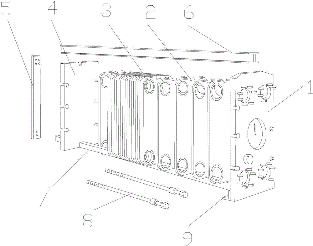
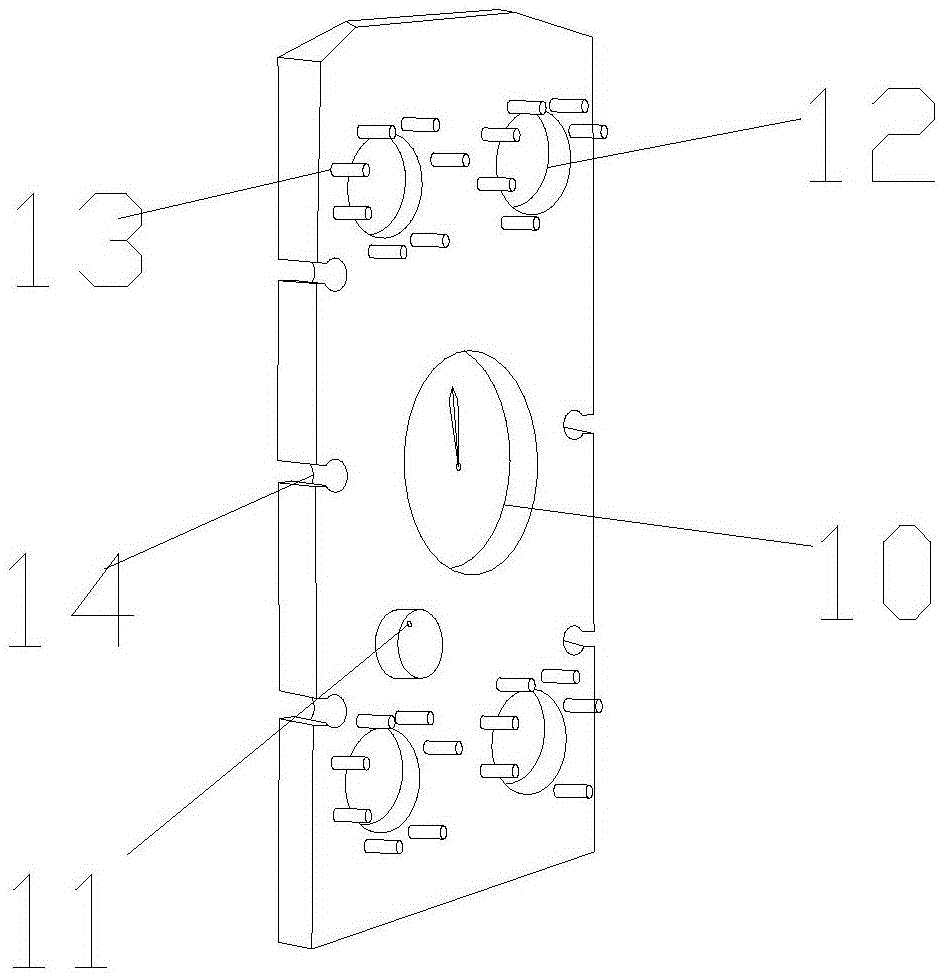
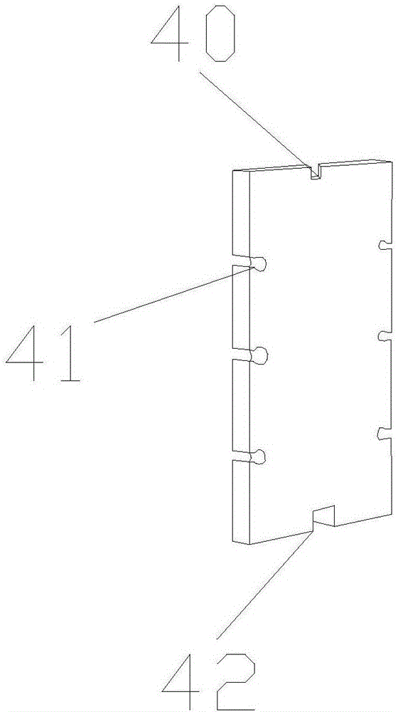
[0016] see Figure 1-4 , the present invention provides a technical solution: a plate-type air preheater, the structure of which includes a front plate 1, a heating plate 2, a gasket 3, a rear end plate 4, a pillar 5, an upper guide rod 6, a lower guide rod 7, Locking screw 8 and anchor 9, the front end plate 1 is connected to the heating plate 2, the gasket 3 is arranged on the surface of the heating plate 2, the rear end plate 4 is connected to the heating plate 2, and the pillar 5 is connected to the rear The end plate 4 is connected, the upper guide rod 6 is arranged on the front end plate 1, the heating plate 2, the gasket 3, the rear end plate 4, and the pillar 5, and the lower guide rod 7 is arranged on the front end plate 1, the heating pl...


PUM


Abstract

The invention discloses a plate-type air preheater which structurally comprises a front end plate, heating plates, gaskets, a rear end plate, a stand column, an upper guide rod, a lower guide rod, locking screws and feet. The front end plate is connected with the heating plates. The gaskets are arranged on the surfaces of the heating plates. The rear end plate is connected with the heating plates. The stand column is connected with the rear end plate. The upper guide rod is arranged above the front end plate, the heating plates, the gaskets, the rear end plate and the stand column. The lower guide rod is arranged below the front end plate, the heating plates, the gaskets, the rear end plate and the stand column. The rear end plate is connected with the front end plate in a locked manner through the locking screws. The feet are arranged below the front end plate. The front end plate is provided with a chronometer, a countdown rotary knob, a cold water introducing opening, a pipeline locking screw and a front bolt locking groove. The chronometer is arranged on the surface of the front end plate. According to the plate-type air preheater, by means of the chronometer, the air preheater can plan automatic heating time, and vigor of a user for watching machines is reduced.

Description

technical field [0001] The invention is a plate type air preheater, which belongs to the field of air preheaters. Background technique [0002] The heat transfer process is widely used in industrial production, some are to facilitate the process medium to reach the temperature specified by the production process, so as to facilitate the smooth progress of the production process, and some are to avoid energy waste in the production process. Among the various equipment that realizes the heat transfer process, the waste of steam heating is the most. At present, the control of the steam heating heat exchanger still adopts the traditional control, the flow of the heating steam is used as the adjustment method, and the outlet temperature of the heated process medium is used as the controlled quantity to form a control system. In the process of industrial production, the equipment due to heat exchange is called heat transfer equipment. In the process of heat transfer, the phase c...

Claims


Application Information

Patent Timeline
IPC IPC(8): F28D9/00F28F27/00F23L15/00
CPCF23L15/00F28D9/0043F28F27/00Y02E20/34
Inventor 孙秋梅
Owner 泉州惠安博派信息技术有限公司
Learn More