Eureka AIR delivers breakthrough ideas for toughest innovation challenges, trusted by R&D personnel around the world.

High voltage cable joint temperature measuring device

A technology of high-voltage cables and temperature measuring devices, which is applied in the direction of measuring devices, electrical devices, thermometers, etc., can solve the problems of easy breakage of optical fibers, inability to fundamentally achieve accurate temperature measurement, and limitations, and achieve the effect of accurate measurement

Inactive Publication Date: 2016-12-07
ZHUHAI YADO MONITORING TECH CO LTD
View PDF3 Cites 12 Cited by
  • Summary
  • Abstract
  • Description
  • Claims
  • Application Information

AI Technical Summary

Problems solved by technology

However, in practical applications, the use of a large number of high-voltage cables without optical fibers has become a fact, and the method of implanting optical fibers into high-voltage cables cannot fundamentally solve the problem of online temperature measurement of high-voltage cables; The structure and usage, using optical fiber temperature measurement, the detection value is the temperature of the part where the optical fiber is implanted in the structural layer of the high-voltage cable, rather than the actual temperature of the core conductor inside the middle joint of the high-voltage cable; moreover, the optical fiber implanted high-voltage cable is in the In the process of laying into the ground, it is subjected to strong traction and stretching, as well as bending deformation, the optical fiber is extremely easy to break, resulting in the loss of all functions
Therefore, the technical application of online temperature measurement by implanting optical fibers in high-voltage cables is greatly restricted, and it is impossible to fundamentally meet the requirements for accurate temperature measurement of high-voltage cable intermediate joints

Method used


Image

  • High voltage cable joint temperature measuring device
  • High voltage cable joint temperature measuring device

Examples


Embodiment Construction

[0018] Below, in conjunction with accompanying drawing and specific embodiment, the present invention is described further:

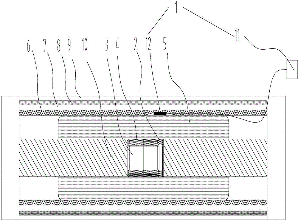
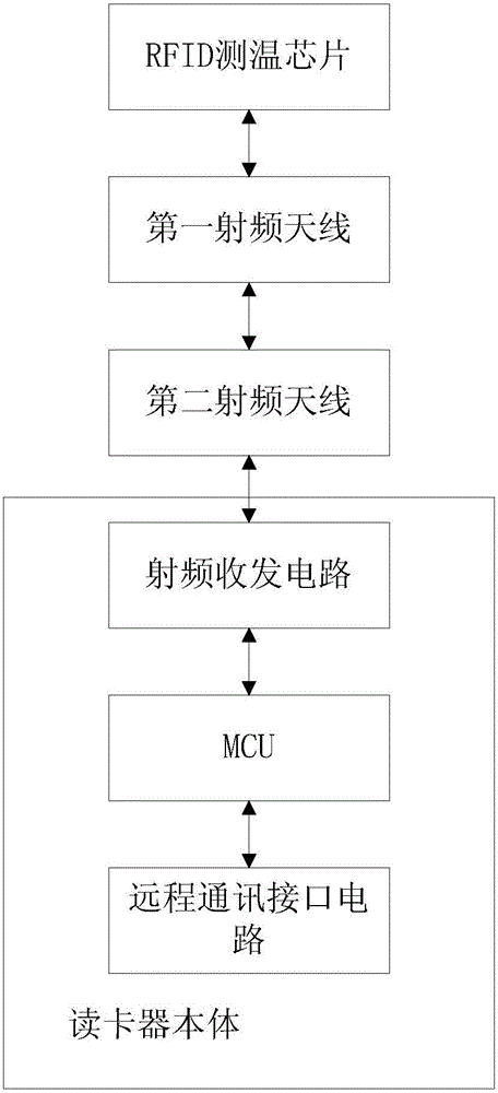
[0019] see figure 1 and figure 2 , the present invention provides a high-voltage cable joint temperature measurement device, which is applied at the joint of high-voltage cables, including a card reader 1 and at least one temperature measurement mechanism 2, and the temperature measurement mechanism 2 is installed on the high-voltage cable insulation layer and wire core 3; the temperature measuring mechanism 2 includes a circuit board, and the circuit board is provided with an RFID temperature measuring chip, a metal block and a first radio frequency antenna, and the card reader 1 includes a card reader body 11 and a second radio frequency antenna 12, and the RFID temperature measurement The chip is connected to the first radio frequency antenna, the card reader body 11 is connected to the second radio frequency antenna 12, the RFID temperature measur...


PUM


Abstract

The invention discloses a high voltage cable joint temperature measuring device, comprising a card reader and at least one temperature measurement mechanism. The temperature measuring mechanism comprises a circuit board; the circuit board is provided with an RFID temperature measurement chip, a metal block and a first radio frequency antenna; the card reader comprises a card reader main body and a second radio frequency antenna; the RFID temperature measurement chip is connected to a first radio frequency antenna; the card reader main body is connected to the second radio frequency antenna; the RFID temperature measurement chip is connected to the metal block; the metal block is in contact with a cable core; the RFID temperature measurement chip is used for detecting a temperature value of the metal block and transmits the temperature value and an ID code corresponding to the RFID temperature measurement chip to the card reader main body through the first radio frequency antenna and the second radio frequency antenna. The RFID temperature measurement core chip converts the radio frequency signal emitted by the card reader to energy to supply power, does not need other driving sources and can accurately measure high voltage cable core temperature.

Description

technical field [0001] The invention relates to the technical field of high-voltage cable safety monitoring in electric power systems, in particular to a high-voltage cable joint temperature measuring device. Background technique [0002] High-voltage cable joints are used to connect high-voltage cable bodies, but they have always been the weak link in the operation of high-voltage cable systems. Among many accidents on high-voltage lines, safety accidents caused by poor contact of high-voltage cable joints are the most common. The increase in temperature of high-voltage cable joints increases the contact resistance at the joints, leading to overheating of high-voltage cable joints, aggravating insulation aging and even causing insulation breakdown, which poses a serious threat to the safe operation of the power system. Therefore, if the temperature change during the operation of the high-voltage cable joint can be effectively monitored in real time, it is of great significa...

Claims


Application Information

Patent Timeline
Patent Type & Authority Applications(China)
IPC IPC(8): G01K7/00
CPCG01K7/00
Inventor 田斌郭晨华杨志强
Owner ZHUHAI YADO MONITORING TECH CO LTD
Why Eureka
Eureka Blog
Learn More