Pulse sequence delay correction method for magnetic resonance imaging

A magnetic resonance imaging and pulse sequence technology, which is applied to magnetic resonance measurement, measurement using an MRI system, and magnetic variable measurement, etc., can solve problems such as occupying large hardware logic resources and limiting the range of delay correction values, etc. Achieve the effect of strong versatility, reducing dosage, and expanding the range of values

Active Publication Date: 2016-12-07
康达洲际医疗器械有限公司
View PDF9 Cites 1 Cited by
  • Summary
  • Abstract
  • Description
  • Claims
  • Application Information

AI Technical Summary

Problems solved by technology

However, the prior art uses deep programmable FIFOs or registers to implement delay correction. In fact, the delay module is constructed based on the hardware logic resources on the pulse sequence generator, and the value range and accuracy of delay correction are between The difference is several orders of magnitude, so using the existing technology to build the delay module will take up a lot of hardware logic resources
In practical applications, the accuracy of delay correction is usually given priority, so the value range of delay correction is limited

Method used


Image

  • Pulse sequence delay correction method for magnetic resonance imaging
  • Pulse sequence delay correction method for magnetic resonance imaging
  • Pulse sequence delay correction method for magnetic resonance imaging

Examples


Embodiment 1

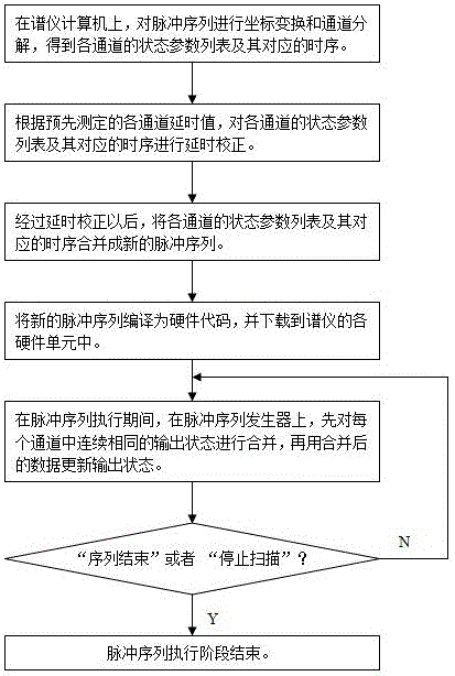
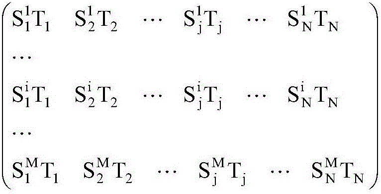
[0019] Before the imaging scan is started, on the host computer, the scanning software converts the scanning scheme set by the user into a corresponding pulse sequence and transmits it to the spectrometer computer. On the spectrometer computer, the pulse sequence compiling software compiles the pulse sequence into hardware codes and downloads them to each hardware unit of the spectrometer. Among them, in the pulse sequence generator, the hardware code is stored in the form of "event|hold time" list. An "event" contains several "bits"; the value of each "bit" is 0 or 1, which represents the output state of a channel in the pulse train generator; "hold time" represents the hold time of the output state, the same "event" "The holding time of each "bit" is equal. The channels of the pulse train generator correspond to the channels of the pulse train.

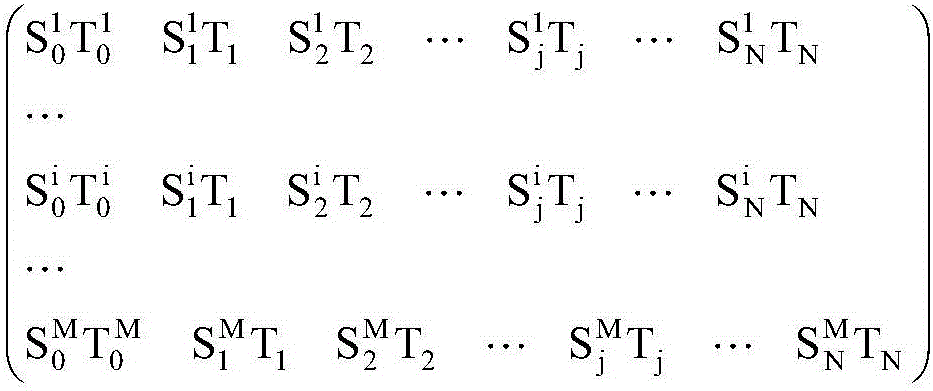
[0020] refer to figure 1 , the present invention performs delay correction before the pulse sequence is compiled into hardware ...


PUM


Abstract

The invention discloses a pulse sequence delay correction method for magnetic resonance imaging. The method comprises the steps of conducting the delay correction before a pulse sequence is compiled into hardware codes; respectively merging continuous and identical output states in each channel on a pulse sequence generator; updating the output state based on merged data; and ensuring the holding time of the output state of each channel to meet the minimum pulse width requirement of the pulse sequence generator after the time delay correction. According to the technical scheme of the invention, the time delay correction is independent of a specific pulse sequence type, thus being strong in universality. The time delay correction is conducted before the pulse sequence is compiled into hardware codes, so that the application amount of hardware logic resources is reduced. On the premise that the hardware complexity is not increased and the time delay correction precision is guaranteed, the value range of the time delay correction is expanded.

Description

technical field [0001] The invention relates to the technical field of magnetic resonance imaging, in particular to a new method for correcting time delay of magnetic resonance imaging pulse sequences. Background technique [0002] The magnetic resonance imaging system mainly includes: magnet subsystem, gradient subsystem, radio frequency subsystem, spectrometer subsystem, main computer and scanning software. Among them, the spectrometer subsystem mainly includes hardware units such as pulse sequence generator, gradient waveform generator, transmitter and receiver, as well as spectrometer computer and pulse sequence compiling software. During the imaging scanning process, that is, during the execution of the pulse sequence, the pulse sequence generator controls other hardware units in the spectrometer to work together. Under the control of the pulse sequence generator, the gradient waveform generator generates the gradient waveform signal required for imaging, the transmitt...

Claims


Application Information

Patent Timeline
Patent Type & Authority Applications(China)
IPC IPC(8): G01R33/54
CPCG01R33/54
Inventor 宁瑞鹏胡坤陈卓
Owner 康达洲际医疗器械有限公司
Why Eureka
Try Eureka