Examination verification apparatus of high-frequency-current-method partial discharge detector and method thereof

A high-frequency current and partial discharge technology, which is applied to measuring devices, instruments, and measuring electrical variables, can solve problems such as the lack of a performance verification platform, hidden dangers in the safe operation of power equipment, and the impact on the effectiveness and reliability of power equipment. Easy to implement, simple and fast debugging, convenient and fast testing process

Active Publication Date: 2016-12-07
HANGZHOU XIHU ELECTRONICS INST
View PDF11 Cites 20 Cited by
  • Summary
  • Abstract
  • Description
  • Claims
  • Application Information

AI Technical Summary

Problems solved by technology

However, due to the uneven performance of high-frequency partial discharge testers and the lack of a unified performance verification platform, the effectiveness and reliability of the partial discharge test results of power equipment are greatly

Method used


Image

  • Examination verification apparatus of high-frequency-current-method partial discharge detector and method thereof
  • Examination verification apparatus of high-frequency-current-method partial discharge detector and method thereof
  • Examination verification apparatus of high-frequency-current-method partial discharge detector and method thereof

Examples


Embodiment Construction

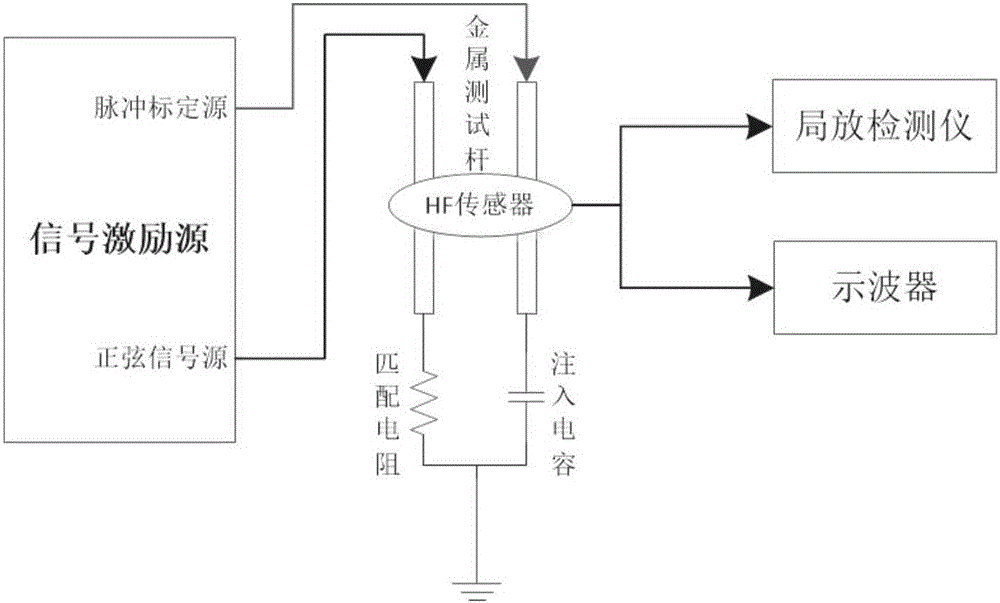
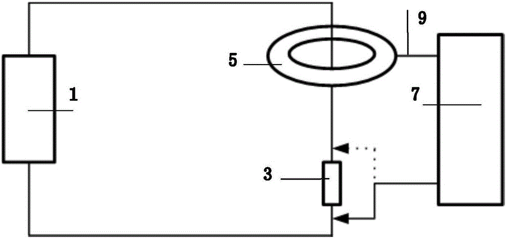
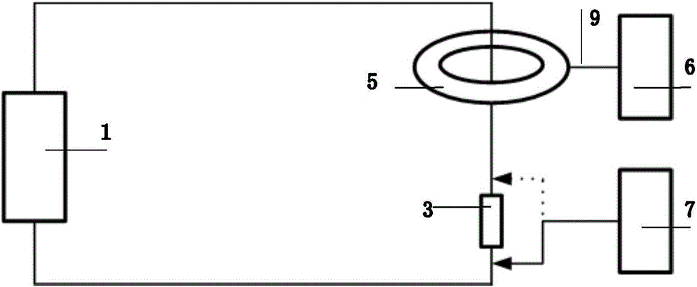
[0055] Such as figure 1 As shown, an assessment and verification device based on the high-frequency current method partial discharge detector, the device includes a signal excitation source, a matching resistor R 0 3. Injection capacitance C 0 4. The first metal test rod, the second metal test rod, an oscilloscope 7, and a 50Ω coaxial cable 9. The instrument under test includes a partial discharge detector 6 and a high-frequency sensor 5; the signal excitation source is a built-in signal source of the device, Divided into sine wave signal source 1 and pulse calibration source 2; the matching resistor R 0 The sine wave signal source and the first metal test rod are connected in series to form a sine signal loop; the injection capacitance C 0 The combination of the pulse calibration source and the second metal test rod in series forms a pulse signal loop; the two metal test rods are used to transmit high-frequency current signals; the high-frequency sensor (HFCT) is inserted t...


PUM

PropertyMeasurementUnit
Bandwidthaaaaaaaaaa

Abstract

The invention discloses an examination verification apparatus of a high-frequency-current-method partial discharge detector and a method thereof. The apparatus comprises a signal excitation source, a matching resistor R0, an injection capacitor C0, a first metal test rod, a second metal test rod, an oscilloscope and a 50omega coaxial cable. A detected apparatus comprises a partial discharge detector and a high frequency sensor. The signal excitation source is a built-in signal source of the apparatus and the signal source is divided into a sine wave signal source and a pulse calibration source. The matching resistor R0 is connected in series with the sine wave signal source and the first metal test rod so as to combine and form a sine signal loop. The injection capacitor C0 is connected in series with the pulse calibration source and the second metal test rod so as to combine and form a pulse signal loop. The apparatus and the method are easy to realize, debugging is simple and rapid, and a test process is convenient and rapid. In the invention, the built-in signal source and an external signal source can be freely selected to carry out signal input. The apparatus and the method are suitable for routine maintenance, testing, verification and other occasions of the high-frequency partial discharge detector in an electric power detection industry.

Description

technical field [0001] The invention relates to the technical field of high-voltage detection, in particular to an assessment and verification device and design method for a high-frequency current method partial discharge detector. Background technique [0002] In the field of high-voltage detection technology, partial discharge occurs inside the power equipment, and the generated pulse current is led to the ground through the grounding down wire, and the current flowing through the grounding wire will drive the change of the magnetic field. By clamping the high-frequency sensor on the grounding down wire Above, the internal coil of the high-frequency sensor is converted into an electrical signal to the partial discharge detection instrument under the action of electromagnetic induction. However, due to the uneven performance of high-frequency partial discharge testers and the lack of a unified performance verification platform, the validity and reliability of the partial di...

Claims


Application Information

Patent Timeline
IPC IPC(8): G01R35/00
CPCG01R35/00
Inventor 陈伟中楼狄张武波曹超刘凤琳陈云鹏杜合胡志鹏厉洋叶新林王光祥
Owner HANGZHOU XIHU ELECTRONICS INST
Why Eureka
Try Eureka