
Mechanical device for automatically detecting construction quality of shield tunnel linings and detection method

A mobile detection device, shield tunnel technology, applied in the direction of tunnel lining, measurement device, tunnel, etc., can solve problems such as difficulty in ensuring the accuracy of radar antenna detection results, affecting detection results, and the inability of lifting rods to ensure verticality.

Active Publication Date: 2016-12-07
SHANGHAI JIAO TONG UNIV
View PDF8 Cites 9 Cited by
  • Summary
  • Abstract
  • Description
  • Claims
  • Application Information

AI Technical Summary

Problems solved by technology

"This device uses a telescopic frame and a lifting rod instead of manual lifting operations. When inspecting the left and right side walls and waist arches, the angle of the radar antenna is changed by adjusting the lifting rod to fit the lining surface. However, the bottom end of the lifting rod is in contact with the lining surface. The support table is fixedly connected. On the premise that the radar antenna is not retractable, if the radar antenna is to fit the lining, the four lifting rods can only be bent inward. After multiple inspections, the verticality and verticality of the lifting rods cannot be guaranteed. Its curvature directly affects the detection results; at the same time, the angle settings of the four lifting rods are still manually adjusted, and human errors cannot be avoided; in addition, the environment of the shield tunnel is not suitable for the entry and exit operations of mobile vehicles
Therefore, the method proposed in the above patent is difficult to guarantee the accuracy of the detection results of the radar antenna, and it is difficult to apply to the quality detection of the shield tunnel lining

Method used


Image

  • Mechanical device for automatically detecting construction quality of shield tunnel linings and detection method
  • Mechanical device for automatically detecting construction quality of shield tunnel linings and detection method
  • Mechanical device for automatically detecting construction quality of shield tunnel linings and detection method

Examples


Embodiment Construction

[0110] The present invention will be described in detail below in conjunction with specific embodiments. The following examples will help those skilled in the art to further understand the present invention, but do not limit the present invention in any form. It should be noted that those skilled in the art can make several modifications and improvements without departing from the concept of the present invention. These all belong to the protection scope of the present invention.

[0111] In this embodiment, the construction of a soil pressure balanced shield tunnel with a diameter of 6m is taken as an example, and the thickness of the lining is 300mm; the center frequency of the selected geological radar is 900MHz, and the size of the radar antenna is 500mm×300mm×210mm, which is separated from the radar host. Connected by cable.

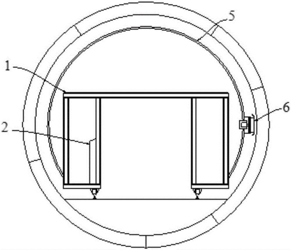
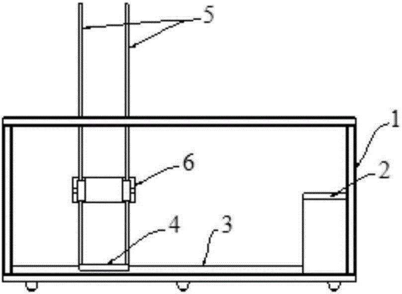
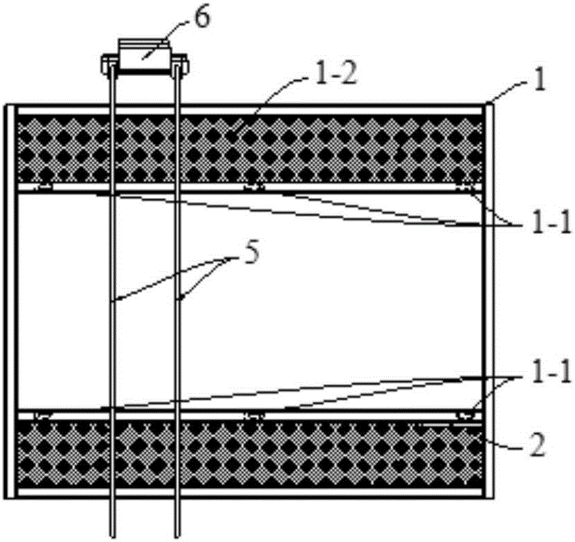
[0112] As shown in Figures 1, 2 and 3, this embodiment provides a mechanical device for automatically detecting the lining quality of a shield tu...


PUM


Abstract

The invention provides a mechanical device for automatically detecting the construction quality of shield tunnel linings and a detection method. The device comprises a detection trolley, a control table, a longitudinal track, a longitudinal moving device, an annular track and an annular moving detection device. The method comprises the steps that the electromagnetic wave speed and center frequency of a radar antenna are determined; the mechanical device and a shield tunneling machine are connected; when the mechanical device moves to the part below a first annular lining of a shield tunnel, the longitudinal moving device is adjusted to make the annular moving detection device located under the central line of the cross section of the first annular lining; a detection line of the shield tunnel lining is determined; proper fitting of the radar antenna in the mechanical device and the surface of the first annular lining is determined; the quality of the first annular lining of the shield tunnel is detected; along with constant advancing of the detection trolley in the mechanical device, the annular moving detection device is made to be located at the central axis of the cross section of a next annular lining by adjusting the longitudinal moving device, and the subsequent lining quality detection work can be completed by repeating the fifth step and the sixth step in sequence.

Description

technical field [0001] The invention relates to the field of detection of the lining construction quality of a shield tunnel, in particular to a mechanical device and a detection method for automatically detecting the construction quality of a shield tunnel lining. Background technique [0002] At present, the quality inspection of shield tunnel lining is mainly ground radar inspection. The basic principle of geological radar detection is to use high-frequency electromagnetic waves in the form of broadband short pulses to send signals underground through the transmitting antenna on the ground, and the receiving antenna receives the part of the electromagnetic wave reflection signal that is reflected back to the ground by the stratum interface or the target body. Then the computer analyzes the time-frequency characteristics and amplitude characteristics of the electromagnetic wave reflection signal to determine the position, geometry and structure of the formation or target. ...

Claims


Application Information

Patent Timeline
IPC IPC(8): G01S13/88G01S13/89E21D11/00E21D9/06
CPCE21D9/06E21D11/00G01S13/885G01S13/89Y02E10/20
Inventor 孔德骏沈水龙刘晓雪张宁吴怀娜
Owner SHANGHAI JIAO TONG UNIV
Learn More