A termite detection device and detection method thereof

A detection device, termite technology, applied in the direction of measuring device, geophysical measurement, radio wave measurement system, etc., can solve the problems of short life of the device, poor applicability, complicated process, etc., and achieve long service life, low false alarm rate, and process simple effect

Active Publication Date: 2019-10-25
ZHEJIANG DEKAN ENVIRONMENT TECH CO LTD
View PDF8 Cites 2 Cited by
  • Summary
  • Abstract
  • Description
  • Claims
  • Application Information

AI Technical Summary

Problems solved by technology

However, this method also has certain disadvantages: (1) The metal wire is easy to oxidize. After a long time, even if there are no termites, it will be broken by itself due to oxidation and other reasons. (2) The life of the device is short and the process is complex; (3) Due to its electrification, it has high requirements on the environment, and it cannot be used in environments with water, humidity, acidic soil, etc., and its applicability is poor.

Method used


Image

  • A termite detection device and detection method thereof
  • A termite detection device and detection method thereof
  • A termite detection device and detection method thereof

Examples


Embodiment 1

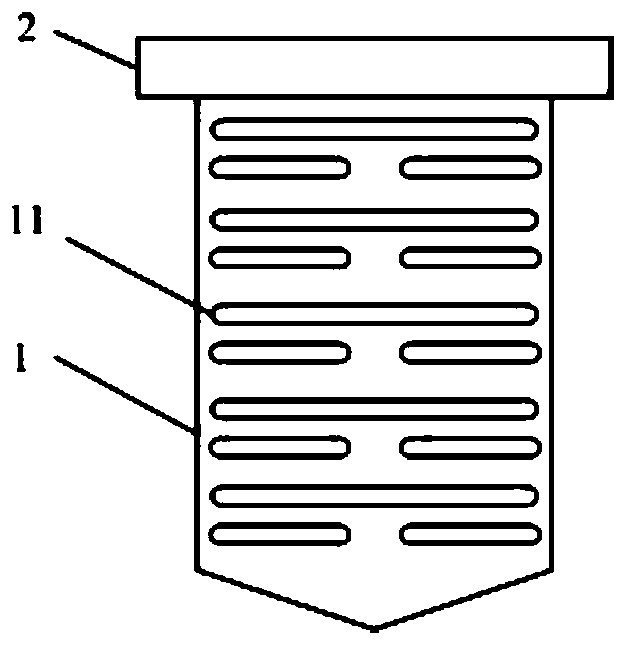
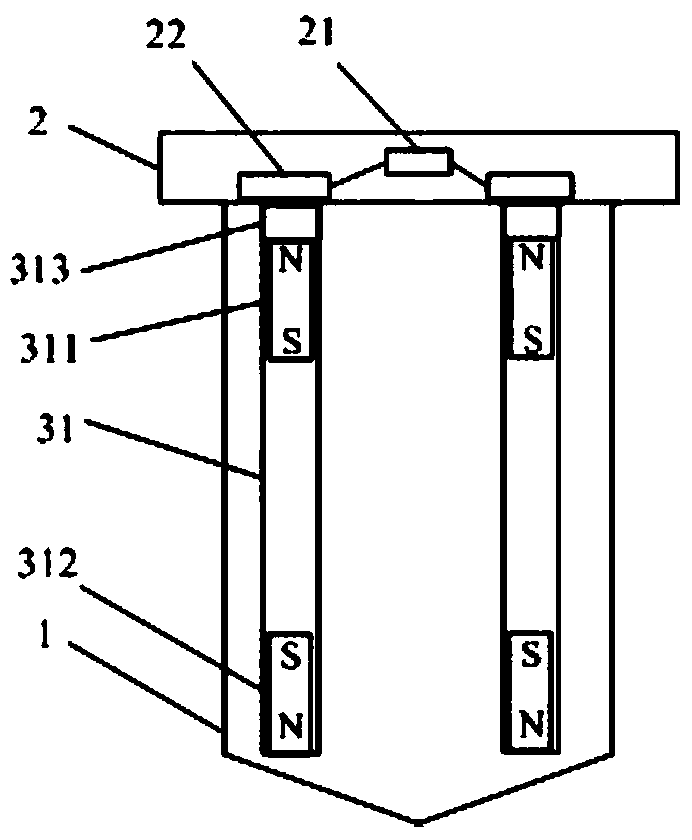
[0054] combine Figure 1-Figure 2 , this embodiment describes the termite detection device of the present invention in detail, and its structural diagram is as follows figure 1As shown, the cross-sectional view is as figure 2 As shown, it includes: a shell 1, a top cover 2 and a bait bar 3, the top cover 2 is covered on the shell 1, the bait bar 3 is located in the shell 1, and the shell 1 is provided with an opening 11. The bait bar 3 is built-in a deep hole 31 with an unreasonable bottom, and a support body is arranged in the deep hole 31 to support the detected body 313 so that the detected body 313 is located in the detection range of the detection switch 22. The detection body 313 descends along with the decline of the supporting body, so that the detected body 313 exceeds the detection range of the detection switch 22; When upward, the detection switch 22 is located above the detected object 312 .

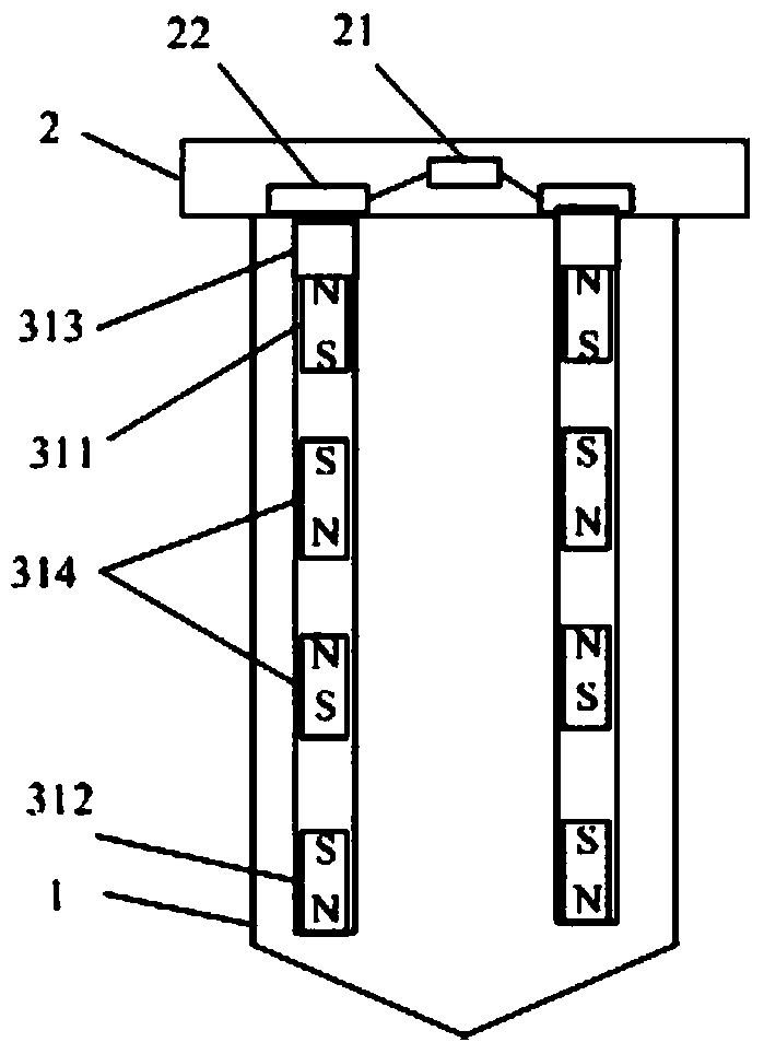
[0055] The support body includes a plurality of magnets. In this emb...

Embodiment 2

[0065] combine Figure 6 , the present embodiment describes in detail the termite detection method of the present invention, which is the detection method of the termite detection system of embodiment 1, which includes the following steps:

[0066] S11: When there are no termites, when the deep hole in the bottom of the bait bar is not bitten by termites, the top magnetic steel supports the object to be detected so that it is within the detection range of the detection switch, and the detection switch is in a conducting state; When there are termites, when the deep hole is bitten by termites, the top magnet is no longer bound by the aperture of the deep hole. Under the action of the magnetic field, the top magnet flips over, is attracted to the bottom of the deep hole by the bottom magnet, and is The supported object to be detected exceeds the detection range of the detection switch, and the detection switch is in the off state;

[0067] S12: Provide wireless power supply for...


PUM


Abstract

The invention discloses a termite detection device and a detection method thereof. The device comprises a housing and bait strips. The housing has an open hole allowing termites to enter, and each bait strip is arranged in the housing and is provided with a circuit board and a detection switch. Each bait strip is internally provided with a deep hole. A liftable support body fills the deep hole. In a normal condition, the top of the support body supports a detected body, the detected body is enabled to be positioned within a detection range of the detection switch, and the detection switch is in a switching-on state. When the deep hole is bitten through by the termite, the top of the support body goes down, the detected body is enabled to go down and to be out of the detection range of the detection switch, and the detection switch is in a switching off state. The circuit board is electrically connected with the detection switch and is used for determining the on-off state of the detection switch. The method comprises a step of determining whether termite exists or not by the on-off state of the detection switch. The detection device is in power-off state in a non-detecting state, the on-off of the detection switch is not dependent on energization, and no environmental requirement is required. The oxidation problem is prevented, and the service life is long.

Description

technical field [0001] The invention relates to the field of termite control, in particular to a termite detection device and detection method. Background technique [0002] Termites are one of the five major pests in the world, especially in tropical and subtropical regions. Termites can eat all plants, and the formic acid secreted in their bodies can also corrode steel bars and denature concrete. Termites have brought a lot of damage to people's daily life, including damage to buildings, dams, crops, books, underground cables, etc. The damage is hidden, such as the damage of termites to buildings, especially to brick and wood structures 1. The destruction of wooden structure buildings is often concealed inside the structure. The surface of the damaged object appears to be intact, but the inside is riddled with holes, often causing the house to collapse, resulting in property loss and casualties. [0003] For a long time, the method of preventing and controlling termites ...

Claims


Application Information

Patent Timeline
Patent Type & Authority Patents(China)
IPC IPC(8): G01V3/00
CPCG01V3/00
Inventor 沈俊峰沈伟强姬汉民
Owner ZHEJIANG DEKAN ENVIRONMENT TECH CO LTD
Why Eureka
Try Eureka