
Modeling method for MJ bolt and nut finite element meshes

A modeling method and finite element technology, applied in special data processing applications, instruments, electrical digital data processing, etc., can solve problems such as complex formulas, poor calculation accuracy, and inability to expand, and achieve the effect of improving calculation accuracy and avoiding errors

Active Publication Date: 2016-12-07
BEIJING INST OF STRUCTURE & ENVIRONMENT ENG +1
View PDF4 Cites 17 Cited by
  • Summary
  • Abstract
  • Description
  • Claims
  • Application Information

AI Technical Summary

Problems solved by technology

However, the formula of this method is relatively complicated and requires node merging and elimination; the patent applied by Xi'an Jiaotong University Hong Jun et al., patent application number: 201110302715.9, although the grid contour node method is used, this method can only describe 17 axial points within the pitch A limited number of grids, and for bolts or nuts with large engineering diameters, the number of grids will be small and the calculation accuracy will be poor
And it cannot be extended to practical engineering problems such as left-handed, right-handed and work difference

Method used


Image

  • Modeling method for MJ bolt and nut finite element meshes
  • Modeling method for MJ bolt and nut finite element meshes
  • Modeling method for MJ bolt and nut finite element meshes

Examples


Embodiment Construction

[0033] The technical solution of the present invention will be described in further detail below in conjunction with the accompanying drawings and specific embodiments. Apparently, the described embodiments are only some of the embodiments of the present invention, not all of them. Based on the embodiments of the present invention, all other embodiments obtained by persons of ordinary skill in the art without making creative efforts belong to the protection scope of the present invention.

[0034] In the first step, the geometric characteristics of bolts and nuts are summarized:

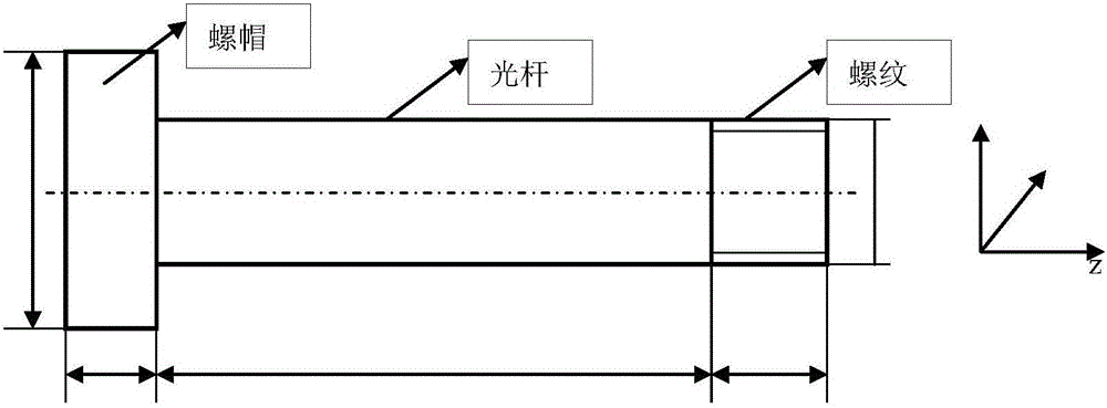
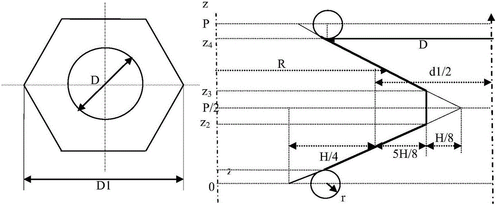
[0035] According to the geometric characteristics of bolts and nuts, the bolt nut area, screw rod area and thread area are summarized, where the thread length is L1, the polished rod length is L2, the nut thickness is L3, and the nut diameter is D2; the hexahedron and thread area of ​​the nut, among which D is the nominal diameter of the thread, and D1 is the outer diameter of the nut; generally, th...


PUM


Abstract

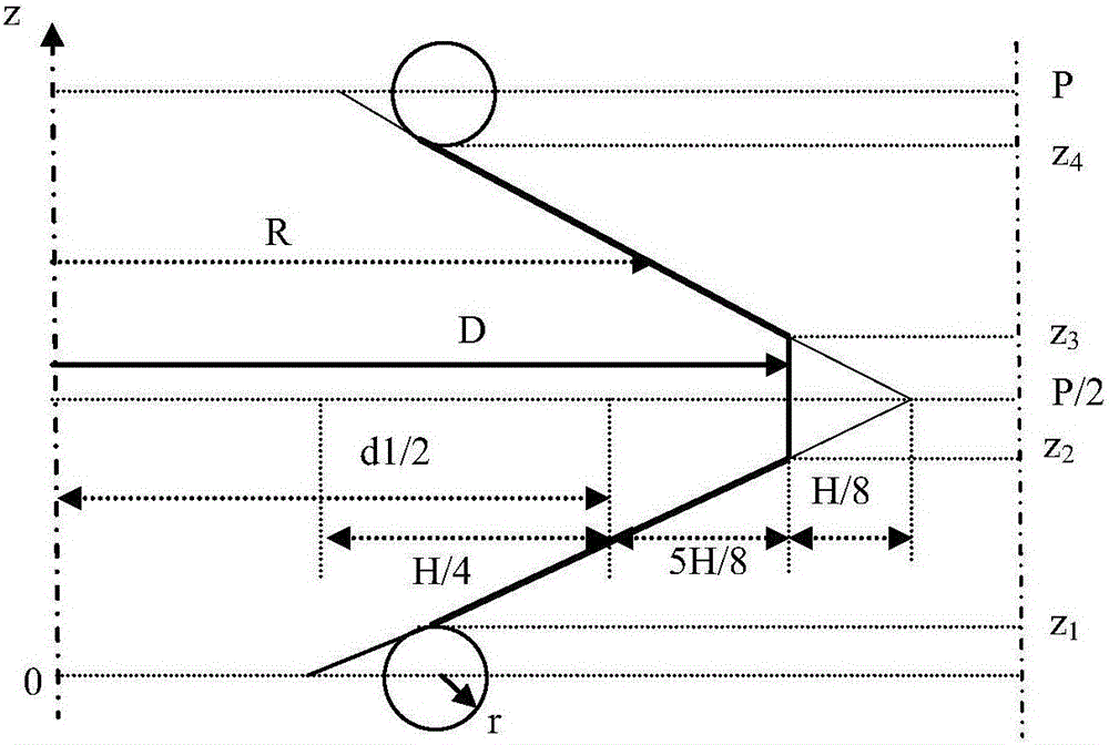
The invention discloses a modeling method for MJ bolt and nut finite element meshes. The method comprises the following specific steps: I, summarizing geometrical features of a bolt and a nut; II, performing mathematical description on a thread zero-position section of the bolt; III, performing mathematical description on a thread zero-position section of the nut; IV, generating unthreaded region finite element meshes of the bolt and the nut; and V, generating thread node offsets of the bolt and the nut, and performing node movement on meshes on threads in order to obtain a threaded bolt. Through adoption of the modeling method, the MJ bolt and nut finite element meshes with threaded structure features can be generated rapidly and effectively. The meshes are hexahedron co-node meshes, so that errors caused by adoption of a TIE command or a tetrahedron mesh can be effectively avoided, and the calculation accuracy is increased greatly.

Description

technical field [0001] The invention belongs to the field of finite element simulation, and in particular relates to an aerospace vehicle MJ bolt and nut finite element mesh generation method. Background technique [0002] Bolted connections are widely used in the development of aerospace structures. From structural system force and moment transmission; structural sealing; structural installations such as inertial groups and cables, bolt connections are widely used. However, due to the relative tightness of the threaded connection, we cannot directly measure it. We can only indirectly measure the deformation and sliding of the overall structure of the bolt by means of force-measuring washers, extensometers, and ultrasonic waves. Especially bad. [0003] The use of finite element simulation is an important means to study its mechanical properties, but the thread division is difficult, and it takes a lot of time to divide the mesh. At present, most of them use TIE or tetrah...

Claims


Application Information

Patent Timeline
Patent Type & Authority Applications(China)
IPC IPC(8): G06F17/50
CPCG06F30/23
Inventor 张明利荣克林刘桢贾亮侯传涛王竞男
Owner BEIJING INST OF STRUCTURE & ENVIRONMENT ENG
Learn More