Automatic paint removing machine

A paint stripping and automatic technology, applied in the manufacture of motor generators, electromechanical devices, electric components, etc., can solve the problems of poor paint stripping quality, low efficiency, complicated coil winding, etc., to achieve compact equipment structure, simple and safe operation, The effect of high paint stripping efficiency

Inactive Publication Date: 2016-12-07
深圳市慈源智能设备有限公司
View PDF8 Cites 3 Cited by
  • Summary
  • Abstract
  • Description
  • Claims
  • Application Information

AI Technical Summary

Problems solved by technology

[0002] Coils are widely used in the fields of electronics and motors. Coil winding is very complicated, especially for various motor rotors or stators. Before coil winding processing, the insulating paint on the pins on the coil needs to be removed according to production needs. In the traditional technology, the paint stripping of the coil is completely manual operation, the quality of the paint stripping is uncontrollable and the efficiency is low
[0003] A mechanism capable of automatically removing paint has appeared in the prior art, such as a utility model patent with a notification number of CN202308757U, which discloses an automatic paint removing mechanism for a paint remover, including: a frame, a frame mounted on the frame There are at least two cutter heads and a servo motor driving the cutter head. This automatic paint removal mechanism uses the cutter head to scrape off the paint layer on the surface of the enameled wire. When the cutter head moves, it will damage the coil wire and affect the production quality of the coil

Method used


Image

  • Automatic paint removing machine
  • Automatic paint removing machine
  • Automatic paint removing machine

Examples


Embodiment Construction

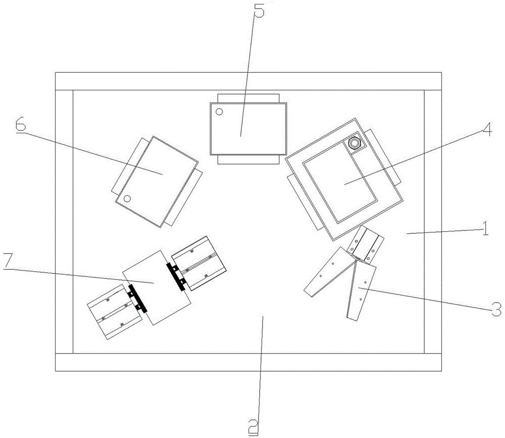
[0025] Such as figure 1 As shown, the automatic paint stripper that the present invention proposes comprises: machine platform 1 and the automatic paint stripping assembly that is located on the machine platform 1, is also provided with upper and lower parts district 2 on the machine platform 1, and the automatic paint stripping assembly includes: for The clipping mechanism 3 for cutting off the legs of the coil pins, the paint stripping mechanism 4 for soaking the coil pins to remove the paint, the cleaning mechanism 6 for cleaning the coil pins and the drying mechanism 7 for drying the coil pins. Preferably, the automatic paint removal assembly also includes a heating and cleaning mechanism 5 located between the paint removing mechanism 4 and the cleaning mechanism 6. After the pins of the coil are depainted, they are first cleaned by the heating and cleaning mechanism 5, and then passed through the cleaning mechanism 6 for the second time. Clean, clean better.

[0026] Suc...


PUM


Abstract

The invention discloses an automatic paint removing machine. The automatic paint removing machine comprises a machine table and an automatic paint removing assembly which is arranged on the machine table, wherein a loading-discharging region is also arranged on the machine table; the mechanisms in the loading-discharging region, and the automatic paint removing assembly are circumferentially arranged around the center of the machine table in sequence; a rotary plate is arranged above the automatic paint removing assembly; at least one suspension frame used for suspending workpieces is arranged on the bottom surface of the rotary plate; the suspension frames are covered with protection boxes; when the suspension frame rotates to a position above one mechanism in the automatic paint removing assembly, a driving assembly pushes the suspension frame to move downwardly until the height of the suspension frame is matched with the mechanism; and when the suspension frame rotates to the loading-discharging region, the corresponding protection box is opened automatically. According to the automatic paint removing machine, the automatic paint removing assembly is circumferentially arranged on the machine table; the workpieces are conveyed to the respective mechanisms in the automatic paint removing assembly in sequence through the rotary plate to be processed; and in addition, the automatic paint removing machine is small in size and high in paint removing efficiency.

Description

technical field [0001] The invention relates to an automatic paint stripper for coils and inner winding stators. Background technique [0002] Coils are widely used in the fields of electronics and motors. Coil winding is very complicated, especially for various motor rotors or stators. Before coil winding processing, the insulating paint on the pins on the coil needs to be removed according to production needs. In the traditional technology, the paint stripping of the coil is completely manual operation, the quality of the paint stripping is uncontrollable and the efficiency is low. [0003] A mechanism capable of automatically removing paint has appeared in the prior art, such as a utility model patent with a notification number of CN202308757U, which discloses an automatic paint removing mechanism for a paint remover, including: a frame, a frame mounted on the frame At least two cutter heads and a servo motor driving the cutter head. This automatic paint stripping mechan...

Claims


Application Information

Patent Timeline
Patent Type & Authority Applications(China)
IPC IPC(8): H02K15/04H01F41/04
CPCH02K15/04H01F41/04
Inventor 谭辉赵玉虎
Owner 深圳市慈源智能设备有限公司
Why Eureka
Try Eureka