
Optical code generator and application thereof

A generator and optical code technology, applied in the field of optical code generators, can solve the problems of high price, high cost, communication, etc., and achieve the effect of long service life, not easy to be damaged, and strong anti-interference ability

Active Publication Date: 2016-12-07
山东大学(威海)
View PDF6 Cites 0 Cited by
  • Summary
  • Abstract
  • Description
  • Claims
  • Application Information

AI Technical Summary

Problems solved by technology

Existing intrinsically safe button switches are expensive, and intrinsically safe button boxes are required to achieve functions that require electrical explosion-proof and isolation; the cost is high
In the working space that requires a high degree of electrical isolation, the electrical equipment needs to meet the intrinsic safety requirements to work normally, and cannot communicate with the outside world quickly and in real time. It can only be conveyed through simple lights and a small amount of information

Method used


Image

  • Optical code generator and application thereof
  • Optical code generator and application thereof

Examples


Embodiment Construction

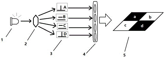
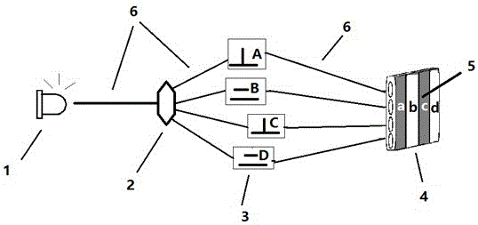
[0013] Such as figure 1 , 2 Described optical code generator is provided with light source 1 and light splitter 2, and light splitter 2 is arranged on the optical path that light source 1 emits light, and each output light path of light splitter 2 is provided with an optical path switch 3, and the light path switch 3 A light projector is arranged on the output light path. When working, the optical splitter 2 divides the optical signal emitted by the light source 1 into multiple parts and outputs it to the optical switch 3. The optical switch 3 can allow or block the passage of the optical signal (such as a through-beam photoelectric switch) to obtain an optical signal that reflects the switch state , the light projector displays the light signal reflecting the switch state as a one-dimensional bar light code or a two-dimensional plane light code. The light projector includes a light concentrator (such as a fiber optic focusing mirror), an information addition board 4 and a p...


PUM


Abstract

The invention relates to an optical code generator, and relates to the technical field of signal transmission devices and application thereof. The optical code generator is provided with a light source and an optical splitter; the optical splitter is arranged on a light path of light emitted by the light source; the optical code generator is characterized in that a light path switch is arranged on each output light path of the optical splitter; a light projector is arranged on the output light path of the light path switch; the light projector comprises an information additional board and a projection board; the information additional board is arranged on the output light path of the light path switch; and the projection board is arranged at the output side of the information additional board. The optical code generator disclosed by the invention is simple in structure and low in cost, and can be used for replacing a lot of electrical switches; the optical code generator can transmit information rapidly in real time in an electrical isolation environment; and the optical code generator is wide in purpose.

Description

technical field [0001] The present invention relates to the field of signal transmission device and its application technology. In detail, it is an optical code generator with simple structure and low cost, which can replace a large number of electrical switches, can transmit information in real time and quickly in an electrically isolated environment, and has a wide range of uses. application. Background technique [0002] We know that in the control system, there are a large number of switches (there are also many switches in small control systems, and the wiring work is calculated in days), and the existence of a large number of switches leads to complicated wiring and wiring of the controller. Medium and large systems use dedicated hubs, signal collectors, etc., which can reduce the number of connections of the main controller and reduce the complexity, but it cannot fundamentally solve the problem. It is still a switch corresponding to a pair of terminals, which cannot ...

Claims


Application Information

Patent Timeline
IPC IPC(8): H04B10/50H04B10/25
CPCH04B10/25891H04B10/50
Inventor 李晓坤王松郭荣生
Owner 山东大学(威海)
Learn More