Suction specific gravity sieve and blown specific gravity sieve combined grain selection machine

A combined and concentrating machine technology, applied in chemical instruments and methods, solid separation, separating solids from solids with airflow, etc., can solve the problems of poor cleaning efficiency and precision, mechanical displacement, and screening Poor effect and other problems, to achieve the effect of screening effect and screening output improvement, slight mechanical shaking, and extended service life

Active Publication Date: 2018-04-13
河南宇虹农业机械有限公司
View PDF6 Cites 0 Cited by
  • Summary
  • Abstract
  • Description
  • Claims
  • Application Information

AI Technical Summary

Problems solved by technology

Some cleaning machines that appear in the prior art can have a certain cleaning effect on the above-mentioned problems, but the cleaning efficiency and precision are not good enough to remove and separate different types of debris well. At the same time, these mechanical structures Complicated, bulky, unreasonable structure setting and layout, mutual influence between cleaning screens, which is not conducive to selection and separation, poor screening effect, low output, mechanical displacement due to vibration in the mechanical working process and comparison of dust in the working process serious

Method used


Image

  • Suction specific gravity sieve and blown specific gravity sieve combined grain selection machine
  • Suction specific gravity sieve and blown specific gravity sieve combined grain selection machine
  • Suction specific gravity sieve and blown specific gravity sieve combined grain selection machine

Examples


Embodiment 1

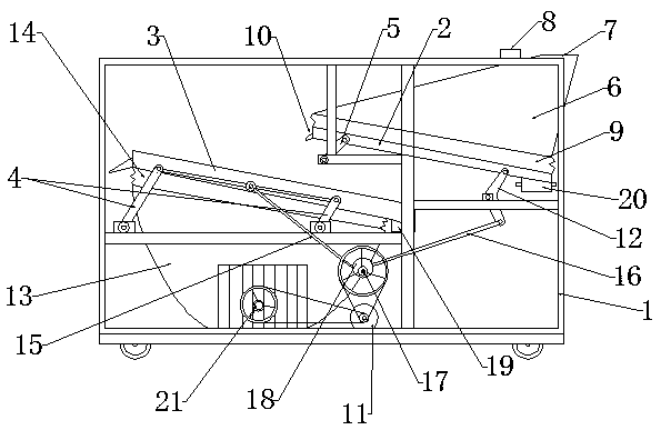
[0030] combined with Figures 1 to 61. The grain classifying machine comprises a frame 1, a suction gravity screen, a blowing gravity screen, a driving device 11, a support arm and a reversing device. The front and bottom of the frame 1, the front part of the suction specific gravity screen overlaps with the rear part of the blowing specific gravity screen in the front and rear direction; , flexible sealing belt 9 and miscellaneous box 20, the air suction specific gravity table 2 is inclined to be set in a high front and low rear mode, and the box body 6 is arranged on the top of the air suction specific gravity table 2, and between the box body 6 and the air suction specific gravity table 2 is provided with A flexible sealing strip 9, a feed pipe 8 is arranged at the middle and rear position above the box body 6, an air exhaust port 7 is arranged at the rear part of the box body 6 above the back and upper part of the suction specific gravity table 2, and an air suction port 7...

Embodiment 2

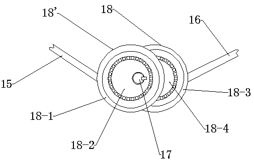
[0034] combined with figure 2 and attached image 3 The eccentric bearing inner ring 18-4 of the air suction specific gravity table and the eccentric bearing inner ring 18-2 of the air blowing specific gravity table are both dislocated and socketed on the drive shaft 17. The misalignment of the eccentric bearing 18 of the suction specific gravity table and the eccentric bearing 18' of the blowing specific gravity table can be adjusted. After adjustment, the drive shaft 17 and the inner ring of the eccentric bearing of the suction specific gravity table 18-4, and the inner ring of the eccentric bearing of the blowing specific gravity table 18-2 can be fixed. , then the highest and lowest relative displacements between the eccentric bearing 18 of the suction specific gravity table and the eccentric bearing 18' of the blowing specific gravity table are determined. The distance between the center of the circle has gone through the maximum distance and the minimum distance, and t...

Embodiment 3

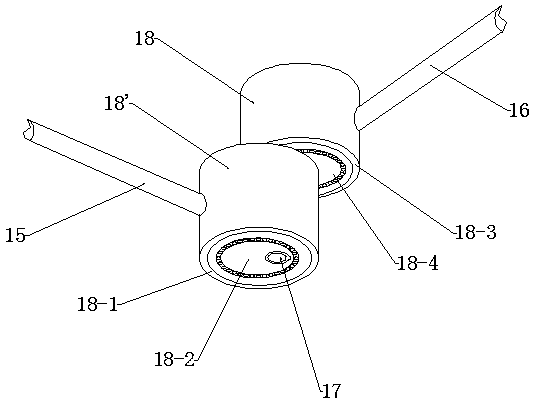
[0036] combined with Figure 4 , 5 and attached Image 6 , the inner ring 18-4 of the eccentric bearing of the suction specific gravity table and the inner ring 18-2 of the eccentric bearing of the blowing specific gravity table are matched and fixed, and the drive shaft 17 is sleeved on the inner rings of the two eccentric bearings. The eccentric bearing 18 of the specific gravity table and the eccentric bearing 18' of the air blowing specific gravity table have the same circle center, and there is no displacement between them. One end of the rod 15 is fixedly connected to the eccentric bearing jacket 18-1 of the air blowing specific gravity table, and the other end of the driving rod 16 of the suction specific gravity table is movably connected to the reversing arm 12, and the reversing arm 12 is movably connected to the suction specific gravity table 2, and the blowing specific gravity table is driven The other end of the rod 15 is movably connected to the blowing specifi...


PUM


Abstract

The invention relates to an air suction gravity sieve and air blowing gravity sieve combined type grain classificatory. An air suction gravity sieve is arranged on the upper back portion of a rack, and an air blowing gravity sieve is arranged on the lower front portion of the rack. The front portion of the air suction gravity sieve and the back portion of the air blowing gravity sieve are overlapped in the front-back direction. An air suction gravity platform supporting arm is rotationally connected to an air suction gravity platform. An air blowing gravity platform supporting arm is rotationally connected to an air blowing gravity platform. One end of an air suction gravity platform driving rod is fixedly connected to an air suction gravity platform eccentric bearing outer sleeve, and the other end of the air suction gravity platform driving rod is movably connected to the air suction gravity platform. One end of an air blowing gravity platform driving rod is fixedly connected to an air blowing gravity platform eccentric bearing outer sleeve, and the other end of the air blowing gravity platform driving rod is movably connected to the air blowing gravity platform. A driving shaft is connected to an air suction gravity platform eccentric bearing inner ring and an air blowing gravity platform eccentric bearing inner ring in a sleeved mode. The air suction gravity platform and the air blowing gravity platform are driven by the driving shaft and move in the opposite directions in the same back-and-forth movement period. The air suction gravity sieve and air blowing gravity sieve combined type grain classificatory of the structure has the advantages of being high in impurity removing efficiency and precision, stable in working process, environmentally friendly and the like.

Description

technical field [0001] The invention relates to an agricultural grain cleaning and beneficiation machine, in particular to a combined grain beneficiation machine of a suction gravitational sieve and a blowing gravitational sieve. Background technique [0002] For modern agriculture, the extensive and extensive application of harvesting machinery has accelerated the industrialized production of agriculture. In the process of harvesting seeds and grains by agricultural machinery, due to the influence of region, climate and variety, the seeds and grains will be harvested. Numerous debris such as weed seeds, pebbles, broken straw, degraded, immature, disease-damaged and moldy seeds and grains are present. Some cleaning machines that appear in the prior art can have a certain cleaning effect on the above problems, but the cleaning efficiency and accuracy are still not good enough, and they cannot remove and separate different types of debris well. At the same time, these mechanic...

Claims


Application Information

Patent Timeline
Patent Type & Authority Patents(China)
IPC IPC(8): B07B4/08B07B11/00
CPCB07B4/08B07B11/00
Inventor 邓新平
Owner 河南宇虹农业机械有限公司
Why Eureka
Try Eureka