Pneumatic plate-shearing machine

A technology of pneumatic shears and pneumatic motors, which is applied in the direction of shearing equipment, shearing devices, metal processing equipment, etc., can solve problems such as large shock vibration and equipment failure, and achieve the effects of improving efficiency, prolonging service life, and reducing power consumption

Inactive Publication Date: 2016-12-14
天津耐斯特宝机电设备有限公司
View PDF0 Cites 2 Cited by
  • Summary
  • Abstract
  • Description
  • Claims
  • Application Information

AI Technical Summary

Problems solved by technology

[0003] The present invention provides a pneumatic shearing machine to solve the problems in the prior art mentioned in the above background art that the traditional electric shearing machine completes the shearing action at one time, and the impact vibration is relatively large during the joint, and the equipment failure is easily caused by overloading.

Method used


Image

  • Pneumatic plate-shearing machine

Examples


Embodiment

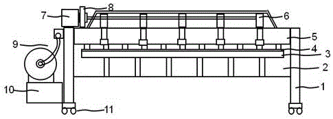
[0019] This embodiment: as figure 1 As shown, a pneumatic shearing machine comprises a frame 2 vertically supported by four support legs 1, the frame 2 includes a horizontal work surface 3, an anvil roller 4 is arranged on the top of the work surface 3, and the work surface 3. A knife rest 5 arranged downwards and perpendicular to the worktable surface 3 is arranged on the rear upper side. The knife rest 5 is axially connected to the horizontally arranged pneumatic motor 7 through the knife rest transmission mechanism 6 connected horizontally at the rear end of the knife rest 5. The pneumatic motor 7 The main shaft is provided with a brake 8, and the pneumatic motor 7 is connected to a pneumatic control box 10 containing a pneumatic system component 9 through a pneumatic conduit.

[0020] The bottom end of the supporting leg 1 is provided with casters.

[0021] The vertical gap between the anvil roller 4 and the work table surface 3 can be adjusted according to the thickness ...


PUM


Abstract

The invention belongs to the technical field of plate-shearing machines, and particularly relates to a pneumatic plate-shearing machine. A pneumatic motor is connected to a pneumatic control box through a pneumatic guide pipe, and a pneumatic system assembly is contained in the pneumatic control box. By means of the pneumatic plate-shearing machine, the problems that in the prior art, due to the fact that a traditional electric plate-shearing machine completes the plate shearing action at a time, impact vibration is large in the junction process, and equipment failures are liable to be caused by overloads are solved. The pneumatic plate-shearing machine has the beneficial technical effects that practicability is high, the plate-shearing efficiency is high, power consumption is reduced, the labor intensity is relieved, and flexibility of plate-shearing machining is improved.

Description

technical field [0001] The invention belongs to the technical field of shearing machines, in particular to a pneumatic shearing machine. Background technique [0002] The plate shearing machine is a machine that uses one blade to make a reciprocating linear motion relative to the other blade to cut the plate. It uses the moving upper blade and the fixed lower blade to apply shear to metal plates of various thicknesses with a reasonable blade gap. The shearing machine is a kind of forging machinery, the main function is the metal processing industry, the products are widely used in aviation, light industry, metallurgy, chemical industry, construction, shipbuilding, automobile, electric power , electrical appliances, decoration and other industries to provide the required special machinery and complete sets of equipment. The existing technology has the problem that the traditional electric shearing machine completes the shearing action at one time, and the shock vibration is l...

Claims


Application Information

Patent Timeline
Patent Type & Authority Applications(China)
IPC IPC(8): B23D15/06B23D15/14
CPCB23D15/06B23D15/14
Inventor 程绍涛
Owner 天津耐斯特宝机电设备有限公司
Why Eureka
Try Eureka