Chamfering equipment for gear production

A technology of chamfering and gears, applied in the field of gear production chamfering equipment, can solve the problems of roughness around the gear teeth, can not be used normally, hurt the operator, etc., to avoid huge errors and achieve the effect of accurate positioning

Inactive Publication Date: 2016-12-14
WUXI PRITEN TRANSMISSION MACHINERY
View PDF7 Cites 5 Cited by
  • Summary
  • Abstract
  • Description
  • Claims
  • Application Information

AI Technical Summary

Problems solved by technology

[0002] A gear is a mechanical element with teeth on the rim that can continuously mesh to transmit motion and power. It is a mechanical part with teeth that can mesh with each other. The application of gears in transmission has appeared very early. More than 300 BC, the ancient Greek philosopher In "Mechanical Problems", Aristotle expounded the problem of using bronze or cast iron gears to transmit rotary motion. At the end of the 19th century, the principle of generative tooth cutting method and special machine tools and tools for tooth cutting using this principle appeared one after another. Gear processing has relatively complete means, and with the development of production, the stability of gear operation has been paid more attention to. After the gear is cut, due to the problems of props and cutting, the teeth and the surrounding area will be rough and have protruding edges and corners. Not only It cannot be used normally, and it will also hurt the operator. It is often necessary to use a fixture when processing gears. To obtain high gear machining accuracy, the positioning accuracy of the fixture must be high. The current gear machining fixture is based on the inner hole of the gear in the center of the fixture. Positioning on the shaft, there is a gap between the shaft center and the inner hole of the gear during positioning, so there will be positioning errors. The waste from the grinding disc in the existing equipment will splash freely with the direction of the grinding disc rotation, which is not only easy to hurt people but also pollutes the environment.

Method used


Image

  • Chamfering equipment for gear production
  • Chamfering equipment for gear production
  • Chamfering equipment for gear production

Examples


Embodiment Construction

[0017] The following will clearly and completely describe the technical solutions in the embodiments of the present invention with reference to the accompanying drawings in the embodiments of the present invention. Obviously, the described embodiments are only some, not all, embodiments of the present invention. Based on the embodiments of the present invention, all other embodiments obtained by persons of ordinary skill in the art without making creative efforts belong to the protection scope of the present invention.

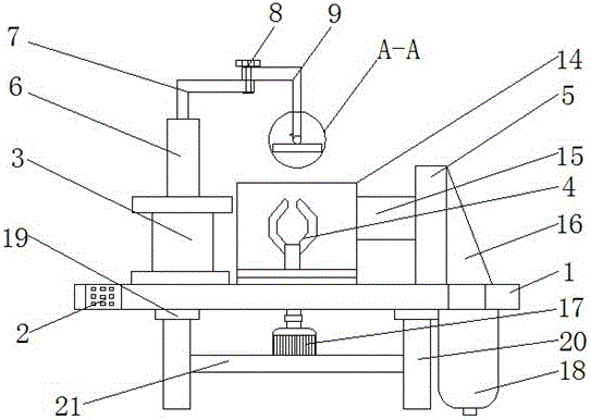
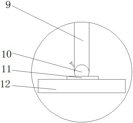
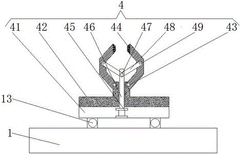
[0018] see Figure 1-5 , the present invention provides a technical solution: a gear production chamfering equipment, including a workbench 1, a controller 2 is fixed on one side of the front surface of the workbench 1, and the top of the base 1 is sequentially provided with first Cylinder 3, clamping device 4 and exhaust fan 5, the top of cylinder 3 is fixed with the first telescopic rod 6, by setting the telescopic rod, no manpower is needed when chamfering,...


PUM


Abstract

The invention discloses chamfering equipment for gear production. The chamfering equipment comprises a working table, a controller is fixedly arranged on one side of the front surface of the working table, and a first air cylinder, a clamping device and an exhaust fan are sequentially arranged at the top of a base from left to right; a first stretchable rod is fixedly arranged at the top of the air cylinder, and a supporting bent rod is fixedly arranged at the top of the first stretchable rod; and the end, far away from the first stretchable rod, of the supporting bent rod is fixedly connected with a rotation bent rod through a screwing bolt, and the position at the end, far away from the screwing bolt, of the rotation bent rod and located above the clamping device is fixedly connected with an angle adjusting device. According to the chamfering equipment for gear production, a pipe, the exhaust fan and a storage chamber are arranged, so that sweeps discharged from a milling disc are completely collected; the stretchable rod is arranged, so that mechanization is achieved; the angle adjusting device is arranged so that gear in various shapes and with different angles can be polished; and the clamping device is additionally arranged, so that huge errors generated during chamfering are avoided.

Description

technical field [0001] The invention relates to the technical field of gear production equipment, in particular to a gear production chamfering equipment. Background technique [0002] A gear is a mechanical element with teeth on the rim that can continuously mesh to transmit motion and power. It is a mechanical part with teeth that can mesh with each other. The application of gears in transmission has appeared very early. More than 300 BC, the ancient Greek philosopher In "Mechanical Problems", Aristotle expounded the problem of using bronze or cast iron gears to transmit rotary motion. At the end of the 19th century, the principle of generative tooth cutting method and special machine tools and tools for tooth cutting using this principle appeared one after another. Gear processing has relatively complete means, and with the development of production, the stability of gear operation has been paid more attention to. After the gear is cut, due to the problems of props and cu...

Claims


Application Information

Patent Timeline
IPC IPC(8): B23F19/12B23F23/00B23F23/06B23Q11/00B23Q1/25
CPCB23F19/12B23F23/00B23F23/06B23Q1/25B23Q11/0046
Inventor 杨国兴
Owner WUXI PRITEN TRANSMISSION MACHINERY
Why Eureka
Try Eureka