A precise grinding method for working face of semi-coupling

A semi-coupling and working surface technology, which is applied in the direction of grinding workpiece brackets, grinding machine parts, grinding/polishing equipment, etc., can solve the problems of difficult control of size and shape and position tolerances, and meet processing requirements, Simple method and high processing efficiency

Active Publication Date: 2018-04-20
HARBIN TURBINE
View PDF5 Cites 0 Cited by
  • Summary
  • Abstract
  • Description
  • Claims
  • Application Information

AI Technical Summary

Problems solved by technology

[0003] The present invention aims to solve the existing problem of difficulty in controlling the dimensions and shape and position tolerances of the working face of the half-coupling when the machine tool has no on-line detection function, and further provides a working surface of the half-coupling. Surface Precision Grinding Method

Method used


Image

  • A precise grinding method for working face of semi-coupling
  • A precise grinding method for working face of semi-coupling
  • A precise grinding method for working face of semi-coupling

Examples


specific Embodiment approach 1

[0031] Specific implementation mode 1: Combination Figure 1~Figure 8 To describe this embodiment, a method for precise grinding of the working surface of a half coupling of this embodiment, the steps are as follows:

[0032] 1. Rough grinding:

[0033] Using mechanical internal tightening tooling 1, the workpiece 100 can be clamped by tightening the first inner hole 100-1 of the workpiece 100;

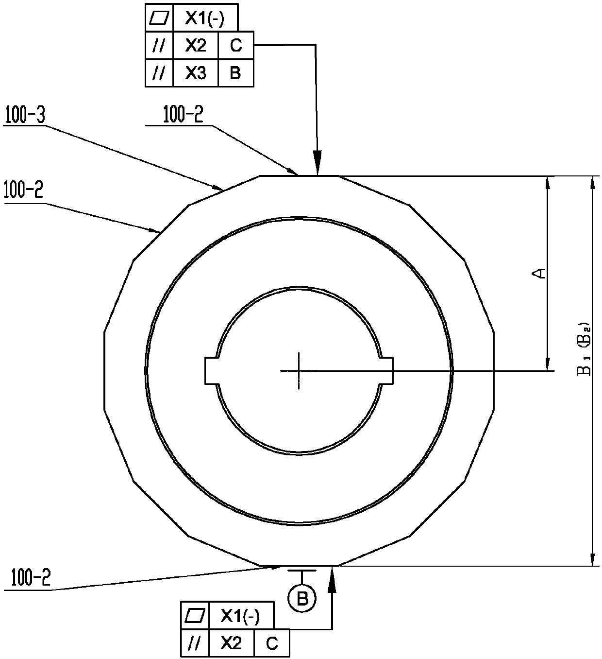
[0034] After clamping, symmetrical grinding is used to rough-grind the working surface 100-2 of the workpiece 100, that is, after grinding a working surface 100-2, move the grinding spindle to start grinding the symmetrical working surface 100-2. After finishing a set of symmetrical working faces 100-2, grind the adjacent working faces 100-2 in the same way until all working faces 100-2 are rough-ground;

[0035] After rough grinding, install a dial indicator on the spindle of the machine tool, use the dial indicator to hit the lowest point 200 of the first inner hole of the workpiece and th...

specific Embodiment approach 2

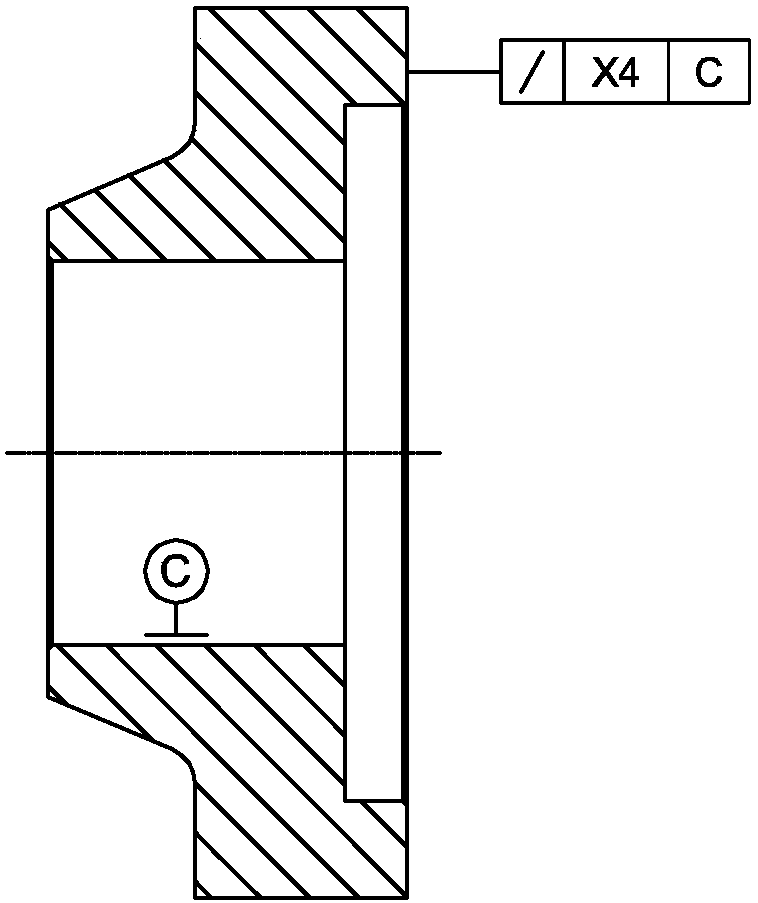
[0051] Specific implementation manner 2: Use a special grinding wheel dressing tool for machine tools to finish the grinding wheel before the finish grinding. Such a design is beneficial to improve the flatness requirement of the working face 100-2. Other components and connection relationships are the same as those in the first embodiment.

specific Embodiment approach 3

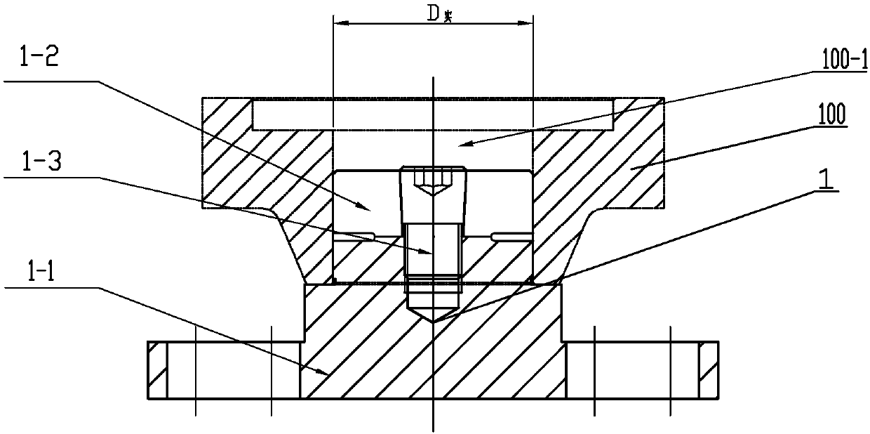
[0052] Specific implementation mode three: combination image 3 , Figure 5 , Image 6 with Figure 7 Explaining this embodiment, the mechanical internal tightening tooling 1 includes a base 1-1, a tightening positioning post 1-2, and a tightening pin 1-3. The upper part of the base 1-1 is processed with a positioning shoulder 1-5, and the base 1 The lower end of -1 is provided with a number of long holes 1-1-1 evenly distributed along the circumferential direction and fixed with the machine tool table by bolts. The tightening positioning column 1-2 is located at the upper end of the base 1-1 and the tightening positioning column 1-2 A taper pin hole 1-2-1 is opened in the center of the spool, and the expansion and positioning column 1-2 is evenly distributed along its circumferential direction with a number of expansion joints 1-2-2 and each expansion joint 1-2-2 points to the axis The center setting, the tightening positioning column 1-2 and the base 1-1 are fixedly connected ...


PUM


Abstract

The invention discloses an accurate grinding method for coupling half working faces and belongs to the field of machining. The problem that under the situation that a machine tool does not have an online detection function at present, it is difficult to control the size and form and location tolerance when the coupling half working faces are ground is solved. Firstly, coarse grinding is conducted, and working allowance is left for accurate grinding; then, the actual accurate grinding allowance is detected in a three-coordinate manner; finally, accurate grinding is conducted, and an outside micrometer is used for auxiliary detection and controlling for the actual removing amount, machine tool machining, a three-coordinate measuring instrument and outside micrometer detection are organically combined, meanwhile, a symmetrical grinding manner is adopted, and the coupling half working faces are accurately ground. The accurate grinding method is used for grinding the coupling half working faces.

Description

Technical field [0001] The invention relates to a grinding method, in particular to a precise grinding method for a working surface of a half coupling, and belongs to the field of mechanical processing. Background technique [0002] For many unit half coupling products ( figure 1 Shown), the shape is a hexadecagon, of which eight faces are the working face 100-2, that is, the mating face. The working face 100-2 and the non-working face 100-3 are interlaced with each other, and the surface roughness of the working face , Flatness, parallelism and other form and position tolerances are extremely high, which can be achieved through reasonable grinding methods, especially the tolerance requirements of each working surface relative to the axis distance A are very strict, and the half coupling axis is a virtual point. Direct measurement cannot be achieved in the machining process, and size control is very difficult when the machine tool has no online inspection system. Summary of the ...

Claims


Application Information

Patent Timeline
Patent Type & Authority Patents(China)
IPC IPC(8): B24B7/07B24B41/06B24B49/04
CPCB24B7/07B24B41/06B24B49/045
Inventor 于克侯姝宏郁洪光龚占利李冬羽姜云涛
Owner HARBIN TURBINE
Why Eureka
Try Eureka