Ridge type planogrinder

A gantry grinder and bridge-type technology, which is applied in the field of machine tools, can solve the problems that parts cannot be ground, the maximum grinding width and length of gantry grinders, and the weight of parts, etc., so as to broaden the processing range, realize precision grinding, The effect of reducing power consumption

Inactive Publication Date: 2013-02-06
WEIHAI HUADONG AUTOMATION
View PDF0 Cites 0 Cited by
  • Summary
  • Abstract
  • Description
  • Claims
  • Application Information

AI Technical Summary

Problems solved by technology

[0002] As we all know, the existing gantry grinders are of movable workbench structure, the grinding wheel is fixed relative to the longitudinal direction, and the parts follow the workbench to reciprocate longitudinally, so that the maximum grinding width, length and part weight of the gantry grinder are all due to structural problems. However, it is limited, resulting in the inability to achieve grinding of parts beyond the range

Method used


Image

  • Ridge type planogrinder

Examples


Embodiment Construction

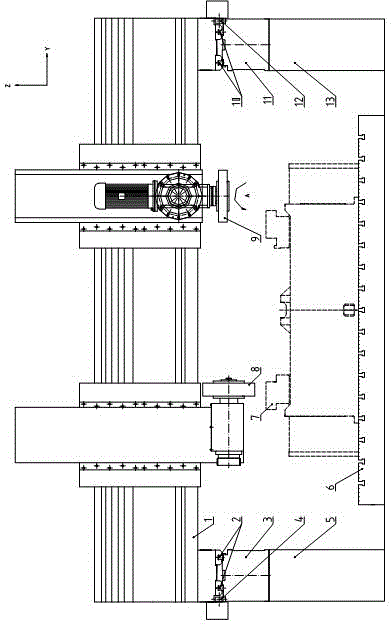
[0011] exist figure 1 Among them, the present invention is provided with left column 5, right column 13, and left bed 3 and right bed 11 are respectively positioned on left column 5 and right column 13, and left bed 3 and right bed 11 are provided with left straight line respectively. Guide rail 2, right linear guide rail 10, beam 1 is located on left linear guide rail 2, right linear guide rail 10, horizontal grinding wheel 8 and vertical grinding wheel 9 are installed on beam 1, workbench 6 is fixed on the ground below beam 1, The processing part 7 is placed on the workbench 6, and the beam 1 is synchronously driven by the left driving device 4 and the right driving device 12.

[0012] The processing parts 7 and the workbench 6 of the present invention are fixed on the foundation, the horizontal grinding wheel 8 and the vertical grinding wheel 9 can move independently on the beam 1 along the Y axis and the Z axis, and the vertical grinding wheel 9 can move along the A The s...


PUM


Abstract

The invention relates to a bridge type planogrinder, belonging to the field of machine tools. The bridge type planogrinder is provided with a left upright post and a right upright post; a left body and a right body are respectively positioned on the left upright post and the right upright post; a left linear guide rail and a right linear guide rail are respectively arranged above the left body and the right body; a cross beam is positioned above the left linear guide rail and the right linear guide rail; the bridge type planogrinder is characterized in that a horizontal abrasive wheel and a vertical abrasive wheel are arranged on the cross beam; a work table is fixed on the ground surface below the cross beam; and the cross beam is synchronously driven by a left side driving device and a right side driving device. The bridge type planogrinder has the beneficial effects that the working range of the planogrinder is widened; accurate grinding and machining of large parts are realized; and simultaneously, the power consumption of the machine tool can be further reduced greatly for energy conservation and environmental protection.

Description

technical field [0001] The invention relates to the field of machine tools, in particular to a bridge-type gantry grinder for grinding large parts, especially super-wide, super-long and super-heavy parts. Background technique [0002] As we all know, the existing gantry grinders are of movable workbench structure, the grinding wheel is fixed relative to the longitudinal direction, and the parts follow the workbench to reciprocate longitudinally, so that the maximum grinding width, length and part weight of the gantry grinder are all due to structural problems. However, due to the limitation, the parts beyond the range cannot be ground. Contents of the invention [0003] In order to overcome the deficiencies of the prior art, the present invention provides a bridge-type gantry grinder, which broadens the processing range of the gantry grinder, realizes precision grinding of large parts, and at the same time can greatly reduce the power consumption of the machine tool, savi...

Claims


Application Information

Patent Timeline
Patent Type & Authority Applications(China)
IPC IPC(8): B24B27/02
Inventor 邱玉良毛维顺刘炳文尹德臻王岩
Owner WEIHAI HUADONG AUTOMATION
Why Eureka
Try Eureka