Turret for turret lathe

a technology for turret lathes and turrets, which is applied in the direction of turning machine accessories, tool holders, manufacturing tools, etc., can solve the problem that complex tools cannot be used in the turret lathe, and achieve the effect of breaking the machining bounds

Inactive Publication Date: 2006-10-10
YAMAZAKI MAZAK KK
View PDF26 Cites 15 Cited by
  • Summary
  • Abstract
  • Description
  • Claims
  • Application Information

AI Technical Summary

Benefits of technology

[0010]The turret body has the function for indexing the tool spindle to which the complex tool is attached by its rotation, and the function for clamping the tool spindle in this way, thereby using the complex tool in a turret lathe. And, time for exchange of the cutting edge by the indexing function (indexing) is shorter than the tool exchange time by an ATC, and the machining efficiency in the turret lathe can be improved thereby.
[0026]In this way, the third means for rotating and driving can index the tool spindle by its rotation, and can successively rotate. Therefore, milling machining by the complex tool is possible in addition to turning machining, thereby further broadening the machining bounds by the complex tool.

Problems solved by technology

But, such complex tool can not be used in the turret lathe since the turret has no indexing function for selecting a desired cutting edge from the complex tool.

Method used


Image

  • Turret for turret lathe
  • Turret for turret lathe
  • Turret for turret lathe

Examples


second embodiment

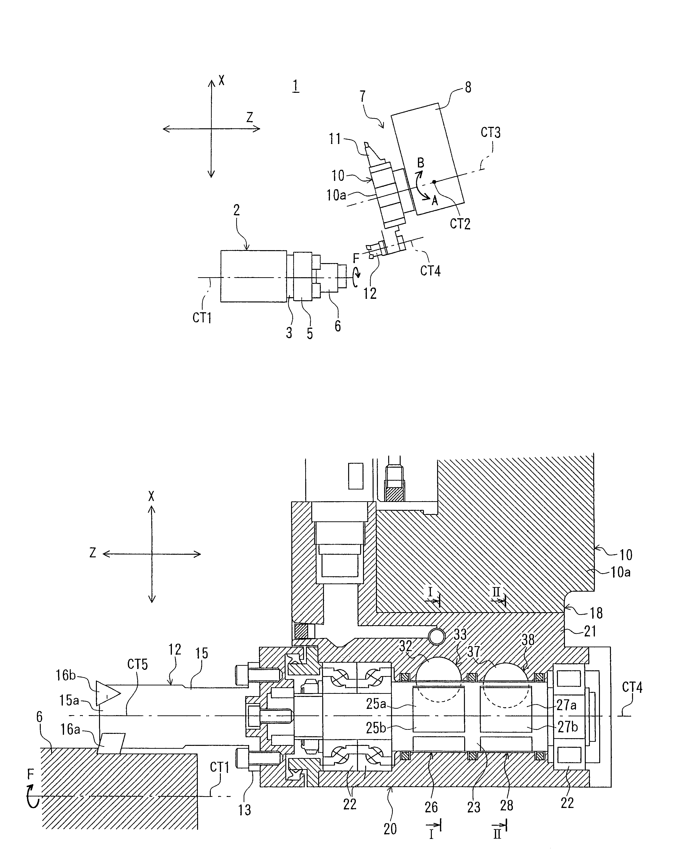
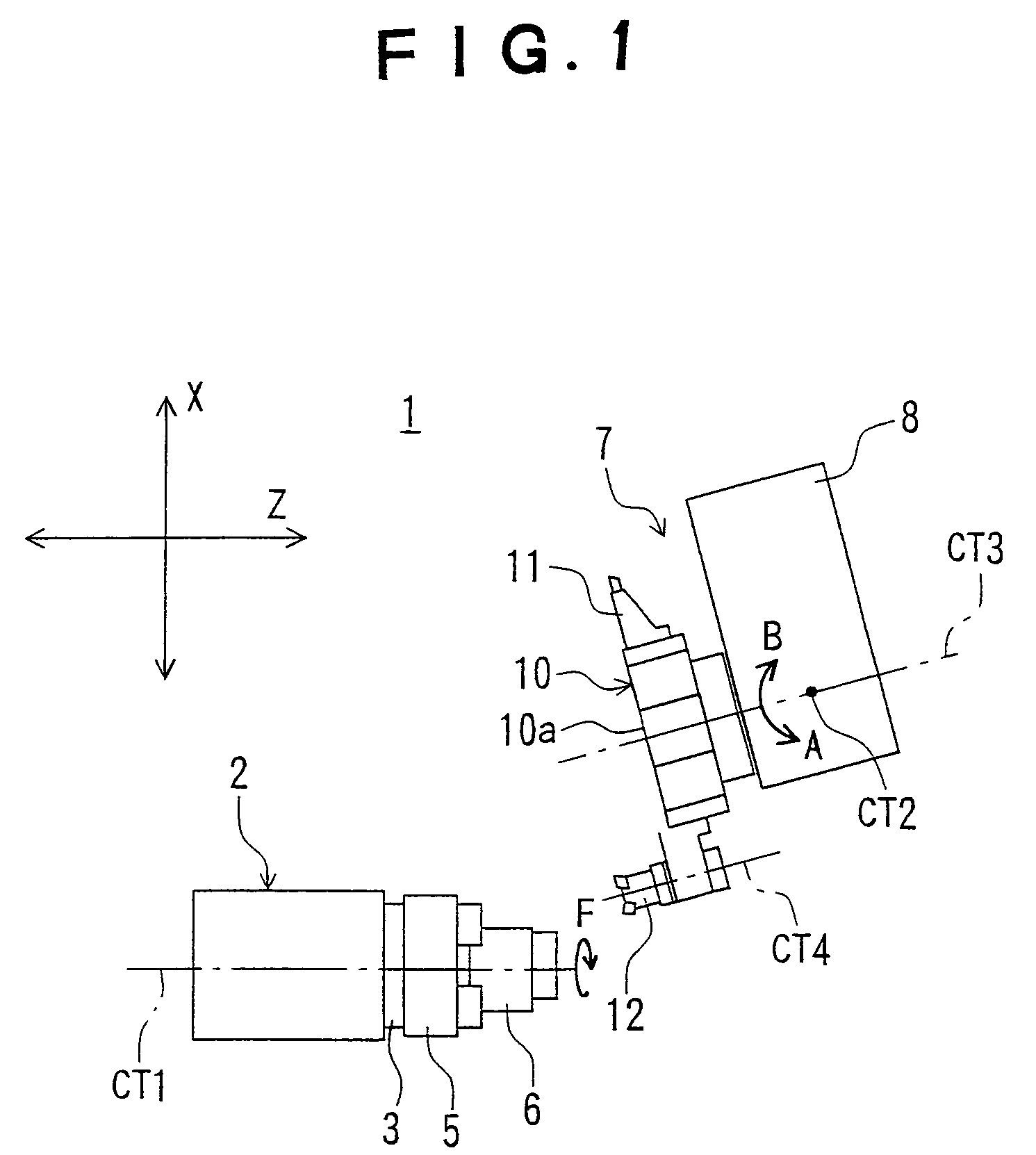
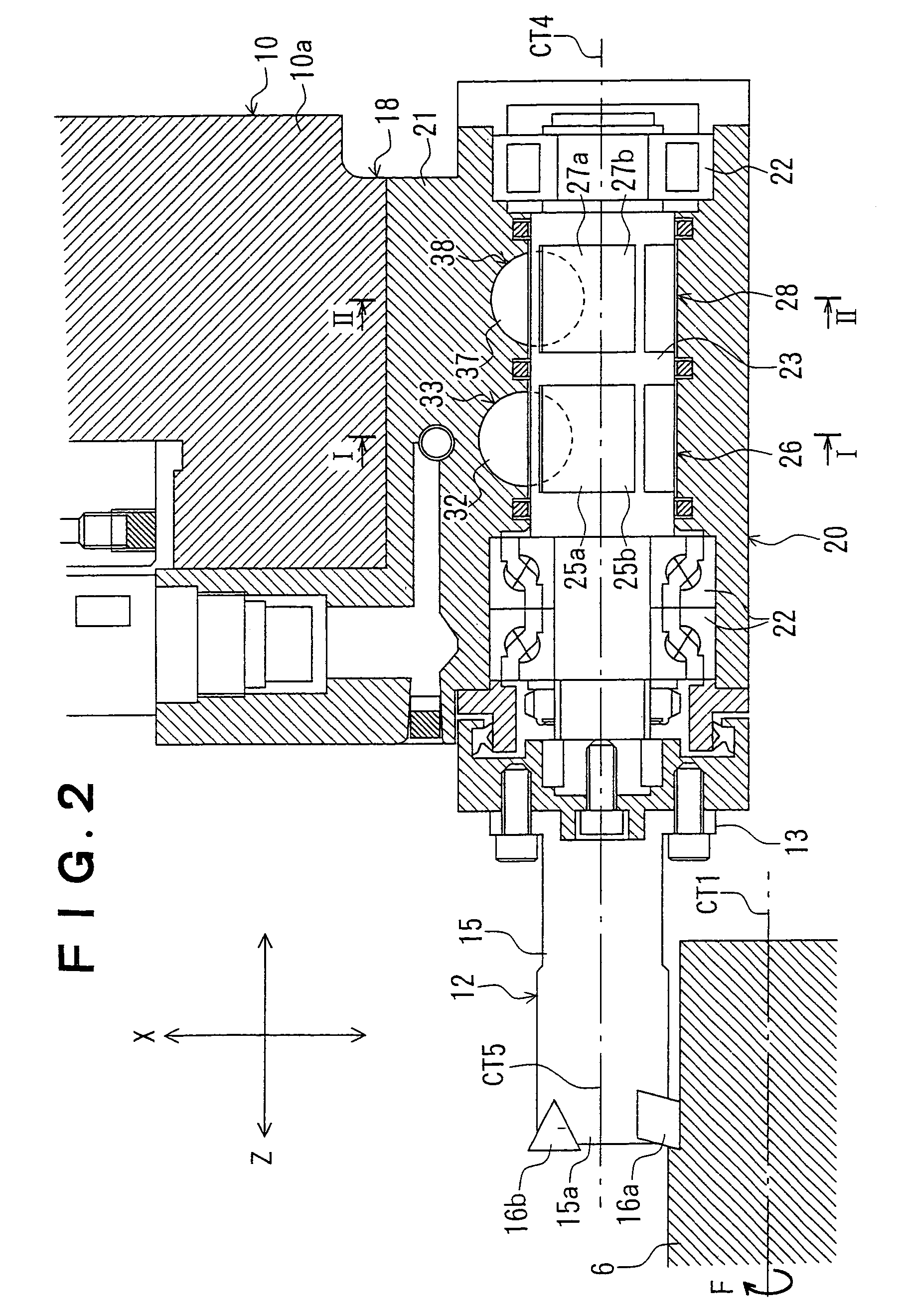
[0067]FIGS. 8 through 13 show the turret according to the invention. FIG. 8 is a plan view showing a positional relation between the spindle stock and the tool rest in the turret lathe, FIG. 9 is a plan view showing B-axis rotational mechanism in the position for attaching tool for a complex tool on the turret according to the invention, FIG. 10 is a plan view showing a portion for attaching tool for the complex tool on the turret according to the invention, FIG. 11 is a schematic view showing turning machining on an outer diameter of the workpiece by the turret according to the invention, FIG. 12 is a schematic view showing turning machining on an end face of an outer diameter by the turret according to the invention, and FIG. 13 is a schematic view showing milling machining on an end face of an outer diameter by the turret according to the invention.

[0068]As shown in FIG. 8, the spindle stock 2 of the turret lathe 1 has the spindle 3 rotatably supported with an axial center CT1 as...

third embodiment

[0087]FIG. 16 shows the turret, and is a plan view showing the position for attaching tool, for attaching the complex tool on the turret according to the invention.

[0088]In FIG. 16, the same reference number is attached to an element the same as one in FIGS. 8 through 10, so that its explanation is omitted. A clutch 42a is formed at one end of the transmission shaft 42 connected with the B-axis indexing motor 41. An adaptor 67 has a base portion 68 attachably and detachably fixed by the position for attaching tool 40 for the complex tool of the turret body 10a of the turret 10, and a transmission shaft 70 is rotatably supported by the base portion 68. A clutch 70a engaging with the clutch 42a is formed at one end of the transmission shaft 70, and the bevel gear 43 engaging with the bevel gear 46 is fixed at the other end. The portion for attaching tool 47 is fixed by the rotational axis 45 connected with the bevel gear 46. The other structure is the same as one as shown in FIG. 10, ...

fourth embodiment

[0091]FIG. 17 shows the turret, and is a plan view showing a portion for attaching tool on the turret according to the invention.

[0092]As shown in FIG. 17, the structure of a portion for attaching tool 71 is that a tool spindle (not shown) is rotatably supported in a housing 72, the tool spindle is rotated and driven by an air motor 73, and a rotational tool, such as a drill 75, is attached to the tool spindle.

[0093]If the portion for attaching tool 71 is detachably attached to the turret 10 or the adaptor 67 in the second and the third embodiments (see FIGS. 9 and 16), and the portion for attaching tool 47 in the respective embodiments is also detachably attached to the turret 10 or the adaptor 67, milling machining with the drill 75 or an end mill (not shown) will be possible by exchanging the portion for attaching tool 47, 71 if necessary in addition to turning machining.


PUM

PropertyMeasurementUnit
angleaaaaaaaaaa
B-axis angleaaaaaaaaaa
angleaaaaaaaaaa

Abstract

A turret body is provided with a tool spindle for detachably attaching a complex tool so as to be freely rotated with an axial center as its center. The turret body is provided with indexing means for indexing the tool spindle, and clamping means for clamping the tool spindle at an indexed position indexed by the indexing means. The turret body has a function for indexing the tool spindle for attaching the complex tool thereto and a function for clamping, thereby using the complex tool in a turret lathe.

Description

BACKGROUND OF THE INVENTION[0001]This invention relates to a turret for turret lathe, and more specifically relates to a turret for turret lathe (simply “the turret” hereinafter) useful for attaching a complex tool installing a plurality of cutting edges thereon.[0002]In a turret lathe, the number of tool installing faces of a turret limits the number of tools to be attached to the turret. For this reason, an ATC lathe equipped with an automatic tool exchanger (ATC), expensive rather than the turret lathe, has been used when the number of the tools necessary for machining is more than the number of the tool installing faces.[0003]In order to soften this limitation, a complex tool having a plurality of cutting edges located on a single body has been proposed. But, such complex tool can not be used in the turret lathe since the turret has no indexing function for selecting a desired cutting edge from the complex tool. Besides, high frequency in exchange of tool increases the time for ...

Claims


Application Information

Patent Timeline
Patent Type & Authority Patents(United States)
IPC IPC(8): B23B29/32B23B29/24B23B21/00B23Q5/04B23Q16/04B23Q16/10
CPCB23Q5/045B23Q16/04B23Q16/102Y10T82/2508Y10T82/2587
Inventor KATOH, KOICHIROKAWASAKI, KAZUOTANAKA, NAOYAKITAYAMA, MINORU
Owner YAMAZAKI MAZAK KK
Why Eureka
Try Eureka