
A clamp for a vehicle transmission valve body

A gearbox and valve body technology, applied in the direction of manufacturing tools, workpiece clamping devices, etc., can solve the problems of not being able to be used as fixtures, achieve good wear resistance, high precision, and reduce errors.

Active Publication Date: 2018-11-13
山东双林新能源科技有限公司
View PDF10 Cites 2 Cited by
  • Summary
  • Abstract
  • Description
  • Claims
  • Application Information

AI Technical Summary

Problems solved by technology

The device disclosed in this prior art can only be used as a tooling fixture when installing the gearbox valve body, but cannot be used as a fixture during transportation, so it is urgent to solve the above problems

Method used


Image

  • A clamp for a vehicle transmission valve body
  • A clamp for a vehicle transmission valve body

Examples


Embodiment Construction

[0029] The present invention will be further described in detail and completely below in conjunction with the embodiments and the accompanying drawings.

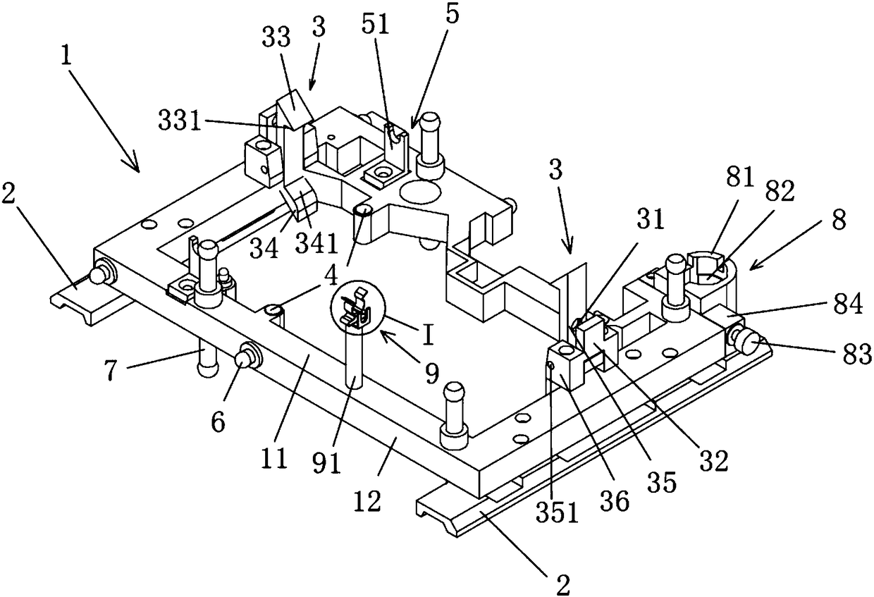
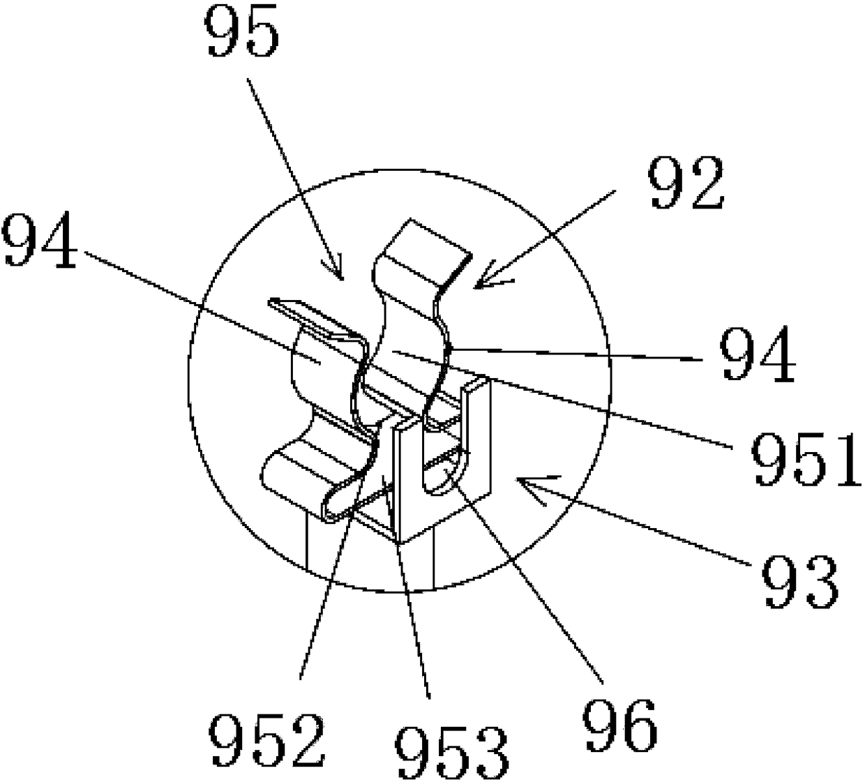
[0030] Such as Figure 1-2 As shown, the present invention provides a clamp for a vehicle gearbox valve body, including a pallet frame 1 for carrying the valve body, a pair of opposite valve body fixing claws 3 are installed on the pallet frame 1, and the valve body The body fixing claw 3 is also connected with a pressing device for bringing a pair of valve body fixing claws 3 closer to each other to generate a pre-tightening force. The pallet frame 1 is also provided with a positioning surface 11 in contact with the valve body. The spacing direction of a pair of valve body fixing claws 3 is parallel to the positioning surface 11, and a valve body positioning pin 4 and a valve core baffle plate 5 are also arranged on the positioning surface 11, and the axis of the valve body positioning pin 4 is perpendicular to The locatin...


PUM


Abstract

The invention discloses a fixture of a car gearbox valve body. The fixture comprises a tray rack used for bearing the valve body, a pair of valve body fixing claws arranged oppositely are installed on the tray rack, and the valve body fixing claws are further connected with a pressing device used for making the pair of valve body fixing claws get close to generate pretightening force. The tray rack is further provided with a positioning surface making contact with the valve body. The clamping direction of the pair of valve body fixing claws is parallel to the positioning surface, and the positioning surface is further provided with a valve body positioning pin and a valve element baffle. The axis of the valve body positioning pin is perpendicular to the positioning surface. The valve element baffle is provided with a stop surface perpendicular to the positioning surface. In this way, the fixture of the car gearbox valve body is simple in structure, firm, reliable, good in abrasion resistance and rigidity, and not prone to deformation; and meanwhile, the positioning reference and the limiting reference coincide, and errors are reduced.

Description

technical field [0001] The invention relates to a clamp, in particular to a tooling clamp for a vehicle gearbox valve body. Background technique [0002] In the automotive transmission industry, due to the design requirements during product assembly, the assembly conditions are very strict. The production lines are equipped with advanced testing equipment to ensure that the accuracy of each product assembled online meets the design requirements. And these devices are not simple, portable testing equipment, but a set of online testing equipment with a complex structure and in line with the production process. The entire testing process is executed by a PLC control program. With the improvement of the automation level, the stability of the clamping and conveying of the valve body fixing fixture needs to be further improved. [0003] When the inventor tested the valve body, the valve body was mainly realized by the robot to clamp, grasp and stack the process. Problems are pro...

Claims


Application Information

Patent Timeline
Patent Type & Authority Patents(China)
IPC IPC(8): B25B11/02
CPCB25B11/02
Inventor 邬建斌王力林慧明
Owner 山东双林新能源科技有限公司
Learn More