Side feeding spiral type continuous extrusion blow molding die head

An extrusion blow molding and spiral technology, which is applied in the field of side-feed spiral continuous extrusion blow molding die, can solve the problems of easy cracking of weld lines and failure to drop test, etc., and achieves good outer surface finish, uniform texture, high intensity effect

Inactive Publication Date: 2016-12-14
SUZHOU JWELL PLASTIC MACHINERY CO LTD
View PDF6 Cites 5 Cited by
  • Summary
  • Abstract
  • Description
  • Claims
  • Application Information

AI Technical Summary

Problems solved by technology

The disadvantage is that the two or four shunt ribs of the shunt bracket cut the molten material and then join together to form a tube blank. There is a weld line in the tube blank. When blowing a larger product, the position of the weld line is easy to break, and the product cannot pass the drop test.

Method used


Image

  • Side feeding spiral type continuous extrusion blow molding die head
  • Side feeding spiral type continuous extrusion blow molding die head
  • Side feeding spiral type continuous extrusion blow molding die head

Examples


Embodiment Construction

[0017] Below in conjunction with the embodiment shown in the accompanying drawings, the present invention is described in detail as follows:

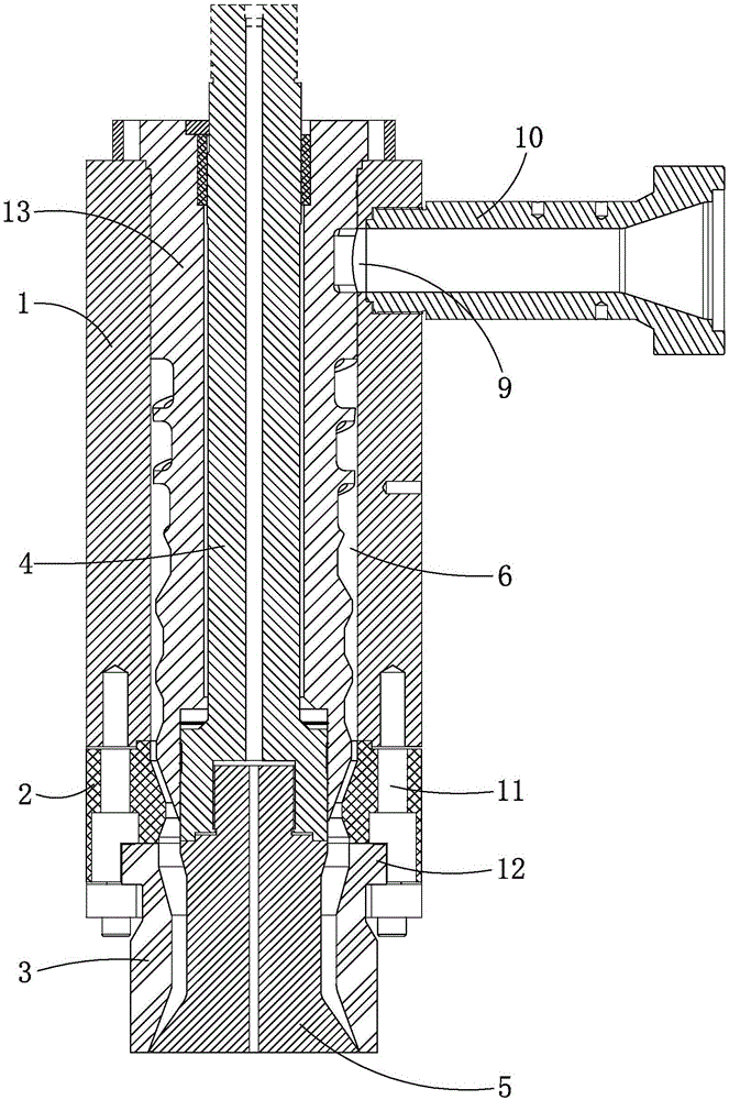
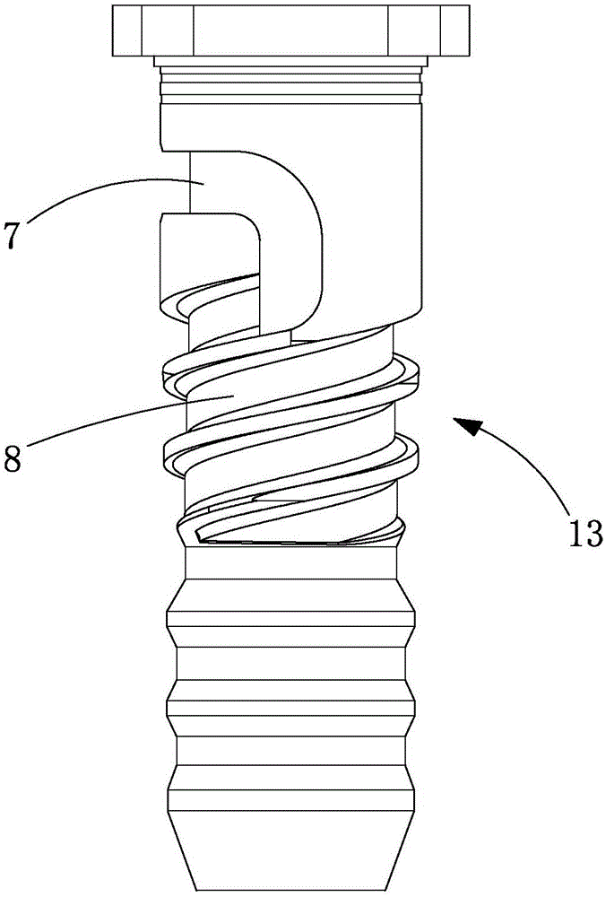
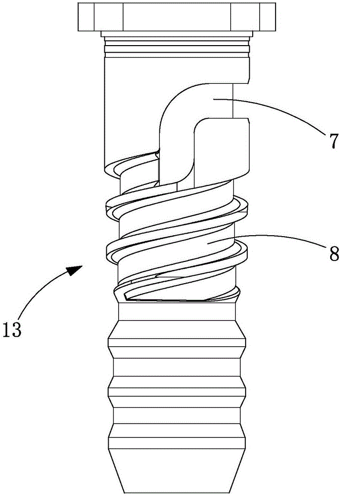
[0018] as attached figure 1 to attach image 3 As shown, a side-feed spiral continuous extrusion blow molding die head includes an outer layer structure and an inner layer structure. The outer layer structure includes an outer mold sleeve 1, an adjusting ring 2 and a mouthpiece that are sequentially connected and installed axially. Die 3, the inner layer structure includes the lifting rod 4 and the mandrel 5 that are axially connected and installed, and the outer mold cover 1, the adjusting ring 2 and the die 3 are all hollow structures in the shaft. The lifting rod 4 is received in the outer mold sleeve 1 and the adjusting ring 2, the mandrel 5 is received in the die 3, and the outer peripheral wall of the lifting rod 4 is sleeved There is a flow-distributing spiral core 13 that can move relatively axially, and a material flow channe...


PUM


Abstract

The invention discloses a side feeding spiral type continuous extrusion blow molding die head. The side feeding spiral type continuous extrusion blow molding die head comprises an outer-layer structure and an inner-layer structure. The outer-layer structure comprises an outer die sleeve, an adjusting ring and an opening die, all of which are axially connected and installed in sequence. The inner-layer structure comprises a lifting rod and a core die which are axially connected and installed. The outer die sleeve, the adjusting ring and the opening die are each of an axis hollow structure. The lifting rod is collected in the outer die sleeve and the adjusting ring. The core die is collected in the opening die. The peripheral wall of the lifting rod is sleeved with a flow diverting spiral core which can axially and relatively move, and a material runner is formed between the outer wall faces of the flow diverting spiral core and the core die and the inner wall face of the outer-layer structure. A material groove is formed in the outer wall face of the flow diverting spiral core. The material groove comprises a feeding groove and multiple parallel spiral material distributing grooves, wherein all the spiral material distributing grooves communicate with the feeding groove and are arranged in parallel. A material is evenly divided into circular-ring-shaped non-weld-line pipe blanks after being diverted, the circular-ring-shaped non-weld-line pipe blanks continuously enter the die head along with the molten material, and the circular-ring-shaped pipe blanks are extruded out of the opening die to form pipe blanks meeting blow molding product technology requirements.

Description

technical field [0001] The invention relates to a side feeding screw type continuous extrusion blow molding die head. Background technique [0002] At present, the existing continuous blow molding dies on the market generally adopt a split bracket structure. The disadvantage is that the two or four shunt ribs of the shunt support cut the molten material and then merge to form a tube blank. There is a weld line in the tube blank, and the position of the weld line is easy to break when blowing a larger product, and the product cannot pass the drop test. Contents of the invention [0003] In view of the above-mentioned technical deficiencies, the purpose of the present invention is to provide a side-feeding spiral continuous extrusion blow molding die head, which can be evenly divided into ring-shaped non-welded line pipe blanks after being divided. The annular tube blank is extruded from the die to form a tube blank that meets the process requirements of blow molding produc...

Claims


Application Information

Patent Timeline
Patent Type & Authority Applications(China)
IPC IPC(8): B29C47/20B29C49/04B29L23/00B29C48/32
CPCB29C48/30B29C48/32B29C49/04B29L2023/00
Inventor 何海潮王宏松
Owner SUZHOU JWELL PLASTIC MACHINERY CO LTD
Why Eureka
Try Eureka