
Beverage Bottle Compression Mechanism

A compression mechanism and beverage bottle technology, applied to presses, manufacturing tools, etc., can solve the problems of compression devices not working, prone to missing inspections, and misjudgment of compression devices, etc., to achieve accurate counting, ensure compression effects, and stable operation Effect

Inactive Publication Date: 2018-03-23
东莞市动能环保科技有限公司
View PDF7 Cites 0 Cited by
  • Summary
  • Abstract
  • Description
  • Claims
  • Application Information

AI Technical Summary

Problems solved by technology

There are several problems in this compression device: 1. When the beverage bottles are put into the recovery device for recycling, it cannot be guaranteed that they are all empty bottles. If there is a lot of liquid left in the bottle, the bottle body may stand up when it falls into the compression device. And the position does not necessarily correspond to the spikes. At this time, the hardest mouth of the beverage bottle and the bottom of the bottle are on the same vertical line. It is not easy to compress it in place with conventional pressure, and it is easy to cause the liquid to be compressed because the bottle body is not pierced during compression. Explosive bottle spraying; 2. When ordinary reflective photoelectric sensors are used on the blanking surface or the discharge port, it is difficult to cover the entire blanking surface. In addition, the irregular blanking of beverage bottles is more prone to missed detection and leakage on the blanking surface. When checking, the compression device will not work, and when the discharge port is missed, it will cause misjudgment by the compression device and repeated compression, which will affect the normal operation of the equipment

Method used


Image

  • Beverage Bottle Compression Mechanism
  • Beverage Bottle Compression Mechanism
  • Beverage Bottle Compression Mechanism

Examples


Embodiment Construction

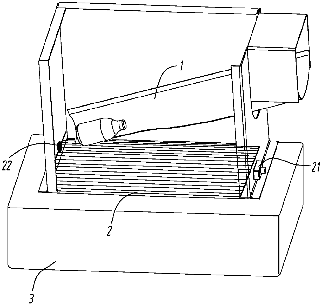
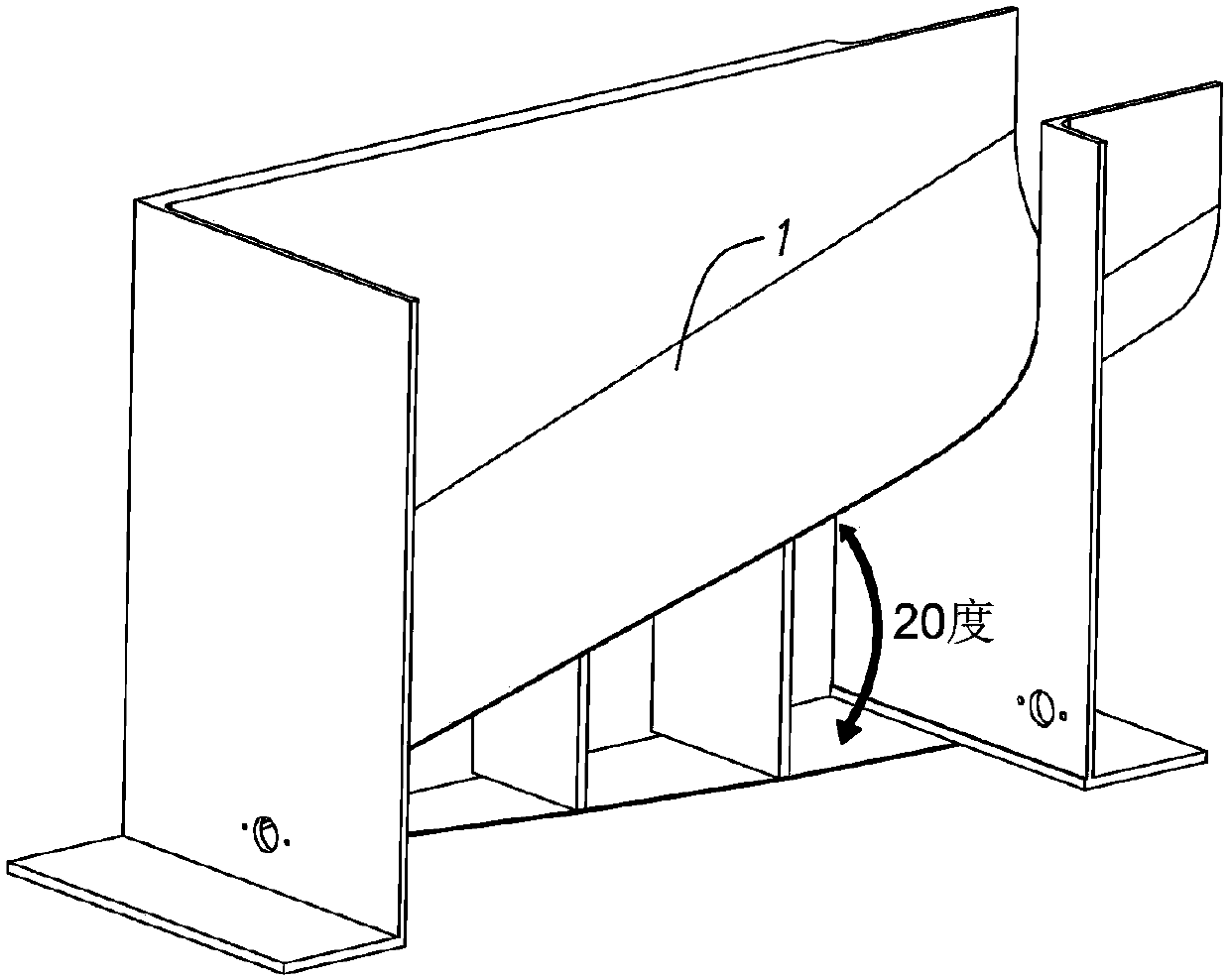
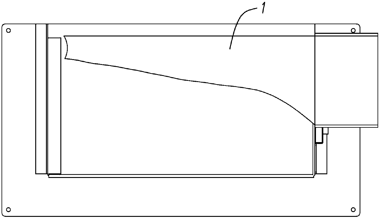
[0017] refer to Figure 1 to Figure 6 A beverage bottle compression mechanism shown includes a blanking chute 1, a blanking detection device 2, a compression device 3, a discharge detection device 4 and a single-chip microcomputer control module; the top surface of the compression device 3 is an unshielded drop Material surface, the bottom surface of the compression device 3 is provided with a discharge port; the blanking chute 1 is located directly above the blanking surface of the compression device 3, and the blanking chute 1 is inclined downward And the cross section is arc-shaped, and the inclination angle of the blanking chute 1 is 20 to 30°; the blanking side of the blanking chute 1 is a beveled surface, and the arc length of the cross section of the beveled surface is determined by The starting end of the blanking chute 1 gradually narrows toward the end; the blanking detection device 2 is arranged on two opposite sides of the blanking surface, including a first linear...


PUM


Abstract

The invention discloses a beverage bottle compressing mechanism. The beverage bottle compressing mechanism comprises a material falling slideway, a material falling detection device, a compressing device, a discharging detection device and a single-chip microcomputer control module, wherein the top surface of the compressing device is a material falling surface, and the bottom surface of the compressing device is provided with a discharging opening; the material falling slideway is located above the material falling surface of the compressing device, the material falling slideway is tilted downwards for 20-30 degrees, the cross section of the material falling slideway is arc-shaped, the material falling side is a diagonal plane, and the arc length of the cross section of the diagonal plane is gradually reduced from the beginning end to the bottom end of the material falling slideway; and each of the material falling detection device and the discharging detection device comprises a physical safety level linear laser source and oppositely arranged light-sensitive resistors, forming parallel laser beams covering the material falling surface and the discharging opening. Bottle bodies slowly slide down from the material falling slideway and gradually fall down in a rollover manner, and the bottle bodies are kept in a horizontal direction when fall into the compressing device, so that the following compressing effect of the compressing device is ensured. Missing detection phenomena do not exist, and the equipment is accurate in counting and stable in running.

Description

technical field [0001] The invention relates to the technical field of beverage bottle recovery devices, in particular to a beverage bottle compression mechanism. Background technique [0002] Traditional recycling devices for plastic bottles generally include squeezing devices and cutting devices. Due to the high power consumption of the cutting devices, bottle caps and bottle stickers made of other materials will be mixed with bottle bodies made of environmentally friendly materials, making the recycling value lower. are extremely small, and are therefore gradually discarded. The Chinese patent with the publication number CN204955488U "A Bottle Body Compression Device for Beverage Bottle Recycling Machine" has the following technical points: a spring is sandwiched between the first compression front plate and the second compression front plate, and the first compression front plate There is a spike array on the top that can pass through the second compression front plate,...

Claims


Application Information

Patent Timeline
Patent Type & Authority Patents(China)
IPC IPC(8): B30B9/30B30B15/30B30B15/32B30B15/06B30B15/26
CPCB30B9/3007B30B9/301B30B9/3014B30B9/3021B30B9/3085
Inventor 王乐新
Owner 东莞市动能环保科技有限公司
Learn More