
Locomotive axle end structure on which six-channel Hall speed sensor can be additionally mounted

A hall speed, six-channel technology, applied in axles, wheels, vehicle parts, etc., can solve problems such as lower reliability, overload, dirt entry, product failure, etc., and achieve the effect of improving safety

Active Publication Date: 2016-12-14
NINGBO CRRC TIMES TRANSDUCER TECH CO LTD
View PDF7 Cites 7 Cited by
  • Summary
  • Abstract
  • Description
  • Claims
  • Application Information

AI Technical Summary

Problems solved by technology

Due to the principle of photoelectricity, the speed sensor and the wheel shaft need to transmit the measured speed through mechanical connection. The square shaft, coupling, bearing and seal of the mechanical transmission parts are always worn under the working state, and they are prone to failure. Regular maintenance is required to replace the worn parts; in addition , based on the principle of photoelectric induction, the inside of the product must be in a dust-free state, but as the product is used, the wear particles caused by rotation continue to increase. When the number of particles reaches a certain level, the light path is blocked, and the product will fail. increase, and the product use environment is generally exposed to the outdoors, rubber components such as rotary oil seals, cable protection hoses, and cable sheaths will inevitably age, and the overall sealing performance of the product will decline, resulting in dust, oil, water, etc. entering the product and causing failure. During operation, there are often frequent shocks, vibrations, overloads, dirt ingress, etc., which seriously affects the reception of sensor signals and greatly reduces its reliability.

Method used


Image

  • Locomotive axle end structure on which six-channel Hall speed sensor can be additionally mounted
  • Locomotive axle end structure on which six-channel Hall speed sensor can be additionally mounted
  • Locomotive axle end structure on which six-channel Hall speed sensor can be additionally mounted

Examples


Embodiment Construction

[0020] The present invention will be further described below in conjunction with the embodiments of the accompanying drawings.

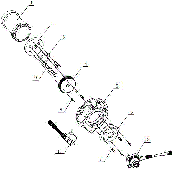
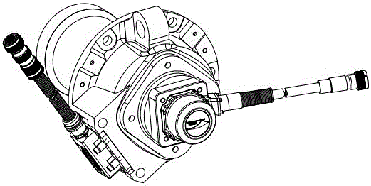
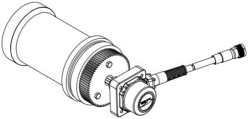
[0021] Such as figure 1 , 2 , 3, the locomotive shaft end structure that can be equipped with a six-channel Hall speed sensor includes an axle shaft 1, a shaft end gland 2, a gear plate 4, a front cover 5, and a rear cover 6.

[0022] The structure of the above-mentioned shaft end gland 2 is as follows: Figure 4 , 5 As shown, a through hole 21 is distributed in the middle, which is used for the positioning of the gear plate 4. Three hexagon head bolt mounting holes 22 and threaded holes 23 have the same diameter and are evenly distributed on the inner circumference of the shaft end gland 2. The shaft end gland 2 An axle locating hole 24 is sunk in the back, and the axle locating hole 24 is used for positioning between the axle end gland 2 and the axle 1, and the axle 1 is placed in the axle locating hole 24.

[0023] The structure of above-menti...


PUM


Abstract

A locomotive axle end structure on which a six-channel Hall speed sensor can be additionally mounted comprises an axle, an axle end gland, a gear plate, a front cover and a back cover. A through hole used for positioning the gear plate is distributed in the middle of the axle end gland, an axle positioning hole in which an axle is positioned is bored in the back of the axle end gland, and the axle end gland and the axle are fixed together; a square hole allowing the installation of a square falcon component is formed in the center of the front of the gear plate, the center of the back of the gear plate is arranged to extend to form a section of positioning shaft for the axle end gland, and the positioning shaft is matched with the positioning through hole in the gear plate on the axle end gland, to position the gear plate; mounting holes for the six-channel Hall speed sensor are formed in the side of the front cover, and the distance between the mounting surface of the mounting holes and the central axis of the front cover not only guarantees the effective induction distance of the six-channel Hall speed sensor, but also can avoid the interference of the sensor and the gear plate; the square falcon component of the six-channel Hall speed sensor is fixed into the square hole of the gear plate when the six-channel Hall speed sensor is fixed on the front of the front cover.

Description

technical field [0001] The invention relates to a locomotive shaft end structure, in particular to a locomotive shaft end structure capable of adding a six-channel Hall speed sensor. Background technique [0002] The speed sensor is installed on the shaft ends of various types of locomotives to provide the running speed and direction of motion for the locomotive, which is an important part of the safe operation of the locomotive. [0003] At present, the six-channel speed sensors installed on the locomotive shaft end are all photoelectric principle speed sensors. The input shaft is connected to the measured wheel shaft. The measured wheel shaft drives the sensor input shaft to rotate. The measured wheel shaft speed is equal to the input shaft speed. The photoelectric effect generates an electric pulse signal proportional to the wheel speed, thereby realizing the function of speed measurement. Due to the principle of photoelectricity, the speed sensor and the wheel shaft nee...

Claims


Application Information

Patent Timeline
IPC IPC(8): B60B35/00B61L25/02G01P3/44
CPCB60B35/00B61L25/021G01P3/44
Inventor 倪大成张燕亮陈增贤刘丹刘志洋
Owner NINGBO CRRC TIMES TRANSDUCER TECH CO LTD
Learn More