A capillary glass tube stacking device and method based on two-dimensional positioning holes of photonic crystal fiber structure

A photonic crystal fiber and capillary glass tube technology, which is applied in the field of fiber manufacturing, can solve the problems of affecting the properties of photonic bandgap fibers, reducing the axial uniformity of photonic bandgap fibers, and taking a long time to achieve mechanical automatic stacking, easy mechanical The effect of automated stacking and low operator requirements

Active Publication Date: 2019-05-03
BEIHANG UNIV
View PDF1 Cites 0 Cited by
  • Summary
  • Abstract
  • Description
  • Claims
  • Application Information

AI Technical Summary

Problems solved by technology

In the production process of photonic bandgap fiber, the production of preform is an essential and extremely important link. The traditional stacking method is to use a hexagonal device for stacking. Post-processing, low efficiency, and glass capillary misalignment, loss, and twisting are prone to occur during the stacking process, which will lead to air hole collapse, loss, and misalignment during the fiber drawing process, greatly reducing the axis of the photonic bandgap fiber. Orientation uniformity, and even seriously affect the properties of photonic bandgap fiber, resulting in greatly reduced yield

Method used


Image

  • A capillary glass tube stacking device and method based on two-dimensional positioning holes of photonic crystal fiber structure
  • A capillary glass tube stacking device and method based on two-dimensional positioning holes of photonic crystal fiber structure
  • A capillary glass tube stacking device and method based on two-dimensional positioning holes of photonic crystal fiber structure

Examples


Embodiment

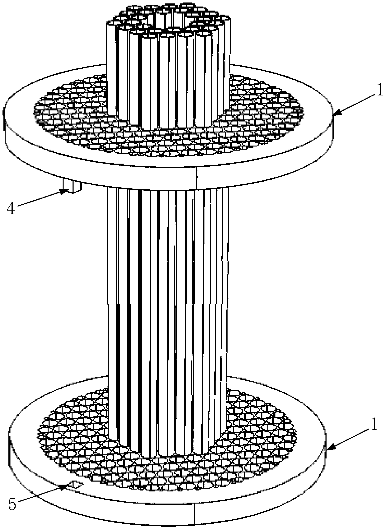
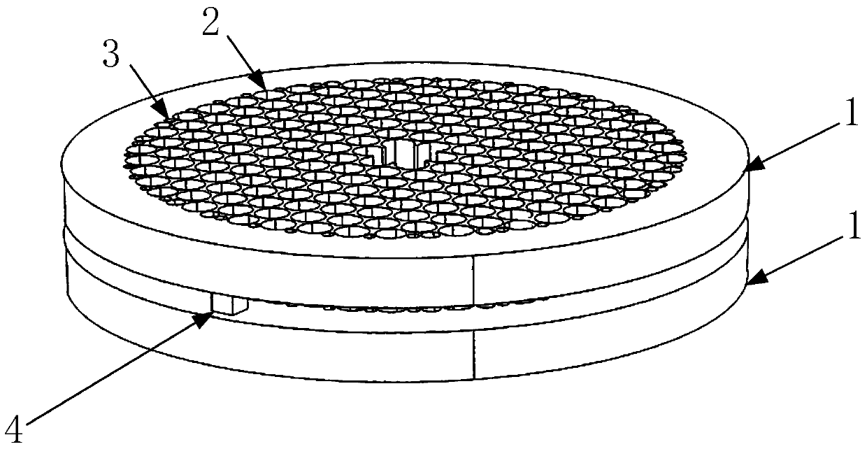
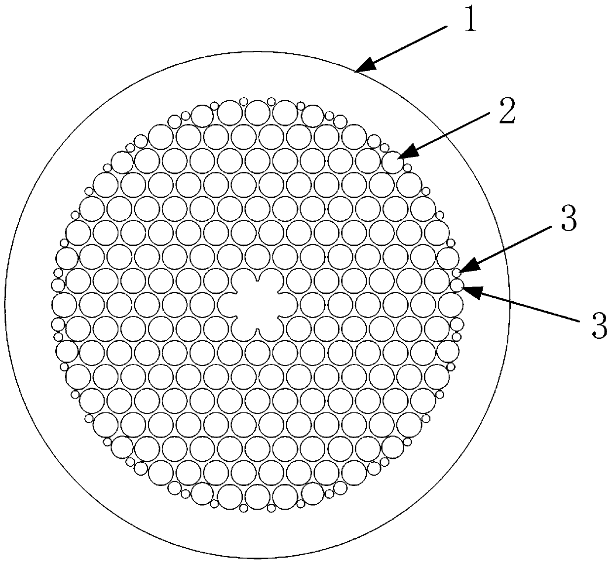
[0027] Such as image 3 As shown, positioning plate 1 is suitable for the photonic bandgap optical fiber with the most complicated preform structure, and its air hole cladding is arranged in a triangular lattice stacking manner, with 180 capillaries, and the middle 7 capillaries are removed, and the outer periphery of the preform There is also a capillary rod with a fixed diameter smaller than the capillary in the circumferential direction; therefore, using the punching technology, according to the structure of the preform on the positioning plate 1, according to the structure of the preform and the size of the capillary, punch holes radially along the positioning plate, and in the two Positioning pins 4 and positioning holes 5 are respectively installed on the positioning plate 1, thereby completing the stacking device corresponding to the photonic bandgap optical fiber. In order to simplify the drilling process and facilitate the removal of the capillary from the two positio...


PUM


Abstract

The invention discloses a photonic crystal fiber structure two-dimensional positioning hole-based capillary glass tube piling device, which comprises two positioning plates; the two positioning plates are arranged in parallel, and optical perforations which are symmetrical are formed in the two positioning plates. Positioning pins and positioning holes are respectively designed at the corresponding positions at the outer edges of the relative side surfaces of the two positioning plates, so as to guarantee the symmetry of the two positioning plates. In use, a capillary tube is inserted in the optical fiber through holes in the two positioning plates to gradually separate the two positioning plates, the two positioning plates are moved to two ends of the capillary tube and can be gradually fixed during the moving process according to practical operation, then two ends of a prefabricated bar are tightly tied with a metal wire and the like, and the device can be taken out from two ends. The capillary glass tube piling device is convenient and easy to operate, has lower requirement on operating personnel, the consistency of the prefabricated bars piled by adopting the device is good, and the manufacturing efficiency of the prefabricated bars are greatly improved.

Description

technical field [0001] The invention belongs to the technical field of optical fiber manufacturing, and relates to a capillary glass tube stacking device and method based on a photonic crystal optical fiber structure two-dimensional positioning hole. Background technique [0002] Photonic crystals refer to materials with different refractive indices arranged periodically in one-dimensional, two-dimensional or three-dimensional ways to form a material with a periodic structure. , that is, a photonic crystal fiber is obtained. At present, photonic crystal fibers are mainly divided into total internal reflection photonic crystal fibers and photonic bandgap fibers. For the total internal reflection photonic crystal fiber, the light wave is still transmitted in the quartz, and the transmission principle is similar to that of the traditional fiber. Compared with the superior environmental adaptability; and the light in the photonic bandgap fiber is limited to transmission in the...

Claims


Application Information

Patent Timeline
Patent Type & Authority Patents(China)
IPC IPC(8): C03B37/012
CPCY02P40/57
Inventor 徐小斌高福宇宋凝芳张春熹张智昊蔡伟
Owner BEIHANG UNIV
Why Eureka
Try Eureka