Oil-gas separator assembly and internal combustion engine

A technology of oil and gas separators and components, which is applied in separation methods, dispersed particle separation, machines/engines, etc. It can solve the problems of short service life of static filter elements, crankcase oil leakage, crankcase pressure increase, etc., to improve service life, The effect is better and the effect of avoiding crankcase oil leakage

Active Publication Date: 2016-12-14
WEICHAI POWER CO LTD
View PDF10 Cites 8 Cited by
  • Summary
  • Abstract
  • Description
  • Claims
  • Application Information

AI Technical Summary

Problems solved by technology

[0004] As we all know, in order to pursue high oil-gas separation efficiency, it is necessary to increase the resistance of the filter element, but this will lead to an increase in the pressure of the crankcase, which will easily lead to oil leakage in the crankcase. On the filter element, the service life of the static filter element is very short, and the filter element needs to be replaced frequently

Method used


Image

  • Oil-gas separator assembly and internal combustion engine

Examples


Embodiment Construction

[0034] One of the cores of the present invention is to provide an oil-gas separator assembly, so as to improve the effect of oil-gas separation and the service life of the filter element without increasing the gas pressure of the crankcase.

[0035] Another core of the present invention is to provide an internal combustion engine with the above-mentioned oil-gas separator assembly.

[0036] In order to enable those skilled in the art to better understand the solution of the present invention, the present invention will be further described in detail below in conjunction with the accompanying drawings and specific embodiments.

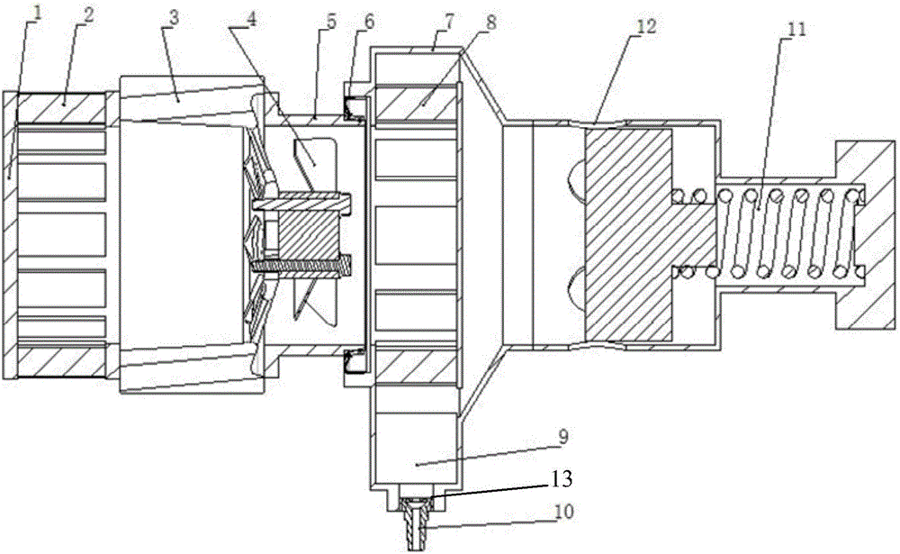
[0037] Please refer to figure 1 , figure 1 It is a structural schematic diagram of the oil-gas separator assembly disclosed in the embodiment of the present invention.

[0038] The oil-gas separator assembly disclosed in the present invention includes a rotary separation section and a static filter section, wherein the rotary separation section includ...


PUM


Abstract

The invention relates to an oil-gas separator assembly which comprises a rotary separation segment and a static filter segment. The rotary separation segment comprises a rotating piece, a rotary framework fixedly arranged on the outer side of the rotating piece, a connecting pipe fixedly connected to the inner side of the rotating piece and a rotary impeller fixedly connected to the rotating piece and located in the connecting pipe. A through hole allowing an oil-gas mixture to pass is formed in the rotating piece. A rotary filter element rotating along with the rotary framework is arranged in the rotary framework. The rotary impeller is used for sucking the oil-gas mixture into the oil-gas separator assembly. The static filter segment comprises a shell in sealing fit with the connecting pipe, static frameworks arranged in the shell, exhaust holes formed in the shell and an oil drainage hole formed in the bottom of the shell. A static filter element is arranged in each static framework. According to the oil-gas separator assembly, the pressure of a crankcase cannot be raised while oil-gas separation is effectively carried out, and meanwhile the service life of the filter elements is effectively prolonged. The invention further discloses an internal combustion engine provided with the oil-gas separator assembly.

Description

technical field [0001] The invention relates to the technical field of internal combustion engine production, in particular to an oil-gas separator assembly and an internal combustion engine. Background technique [0002] During the working process of the internal combustion engine, some of the gas in the combustion chamber will enter the crankcase through the gap between the piston ring and the cylinder liner. These gases contain lubricating oil mist and combustion products of fuel in the combustion chamber. [0003] In order to reduce the consumption rate of engine oil and ensure clean discharge, it is necessary to separate oil and gas from the gas entering the crankcase. At present, the oil and gas separators used in internal combustion engines are generally relatively simple, generally including a housing and a static filter element built in the housing, oil and gas After the mixture enters the oil-gas separator, the oil droplets are absorbed by the filter element, and t...

Claims


Application Information

Patent Timeline
Patent Type & Authority Applications(China)
IPC IPC(8): F01M13/04
CPCF01M13/04F01M2013/0422F01M2013/0438F01M13/0011F01M2013/0433B01D45/14B01D46/0056B01D46/2411B01D46/446B01D50/20B01D46/0036
Inventor 李春锋申加伟李楠
Owner WEICHAI POWER CO LTD
Why Eureka
Try Eureka