Automatic bullet conveying device for mortar

A technology for mortar and bomb feeding, which is applied in the field of automatic mortar feeding devices, and can solve problems such as the failure to fully guarantee the reliability and stability of bomb feeding, the lack of symmetry in the overall structure of the manipulator, and the large trajectory error at the end of the manipulator, etc. problems, to achieve the effect of increasing redundant insurance, reducing assembly complexity, and improving reliability

Inactive Publication Date: 2016-12-14
NANJING UNIV OF SCI & TECH
View PDF8 Cites 10 Cited by
  • Summary
  • Abstract
  • Description
  • Claims
  • Application Information

AI Technical Summary

Problems solved by technology

However, due to the lack of symmetry in the overall structure of the manipulator, the projectile will generate a biased moment during the movement, which will cause the deformation of the manipulator and cause dynamic motion errors.
In addition, because the forearm and the claw pusher will generate a large partial load moment on the large arm, resulting in uneven wear at the joint of the arm, resulting in mechanical vibration during the delivery of the bomb, and the trajectory error at the end of the manipulator becomes larger, which cannot Fully guarantee the reliability and stability of bomb delivery
[0004] Therefore, the problem existing in the prior art is: the automatic bomb delivery device of the mortar has low reliability and poor stability when the bomb is automatically supplied and delivered quickly.

Method used


Image

  • Automatic bullet conveying device for mortar
  • Automatic bullet conveying device for mortar
  • Automatic bullet conveying device for mortar

Examples


Embodiment Construction

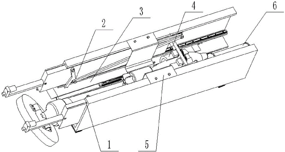
[0027] Such as figure 1 , 2 As shown, the mortar automatic feeding device of the present invention is detachably mounted on the mortar barrel 6, and includes a guide rail system 1, a plane four-bar linkage mechanism 2, a screw slide mechanism 3, and a clamping mechanism 4 and tray 5;

[0028] The clamping mechanism 4 is used to clamp the shells placed on the tray 5, and under the joint action of the planar four-bar linkage mechanism 2 and the screw slide mechanism 3, the shells are sent into the mortar barrel along the rail system 1 within 6.

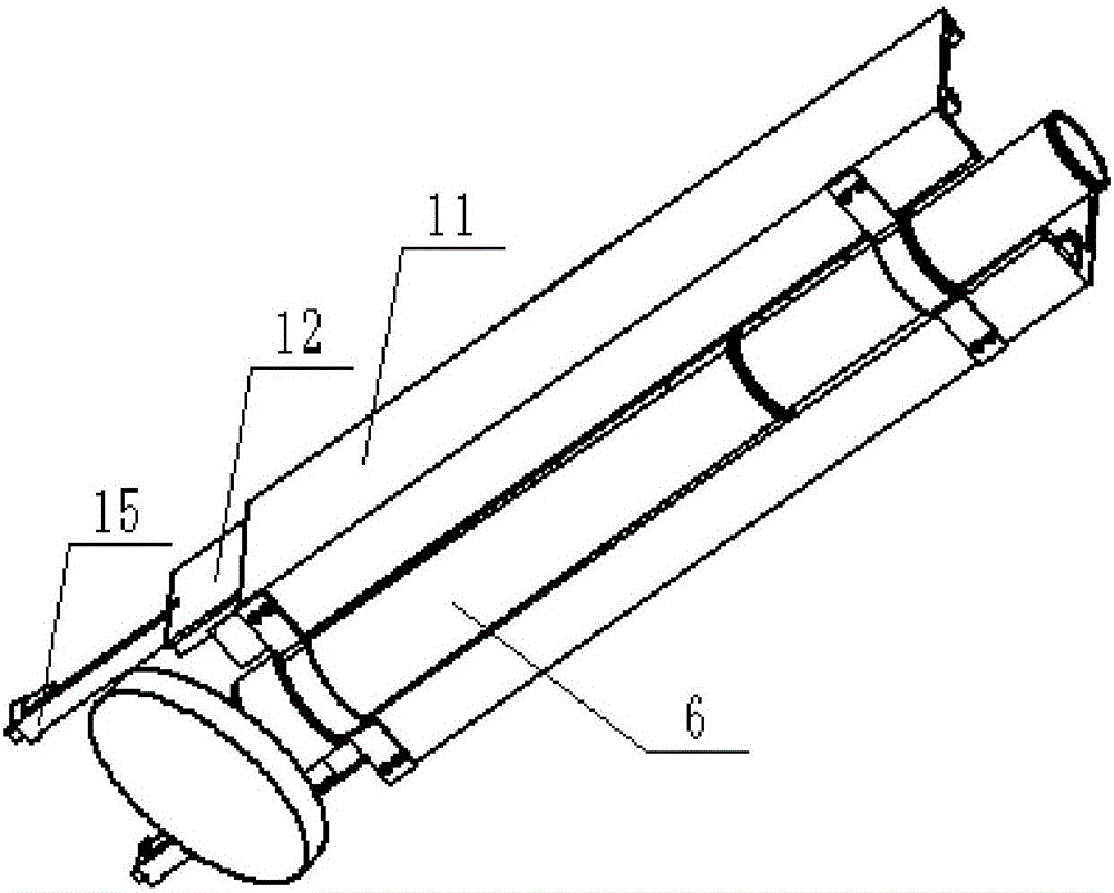
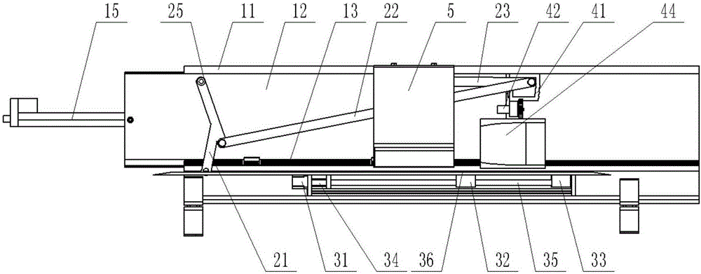
[0029] Such as image 3 , 4 As shown, the guide rail system 1 includes fixed guide rails 11, movable guide rails 12, linear guide rails 13 and optical axis guide rails 14 arranged in pairs relative to the mortar barrel 6, and the cross section of the fixed guide rails 11 is "E" shaped , the openings of the two fixed guide rails 11 are facing each other, the linear guide rail 13 is elongated and fixed on the middle step of the fixed...


PUM


Abstract

The invention discloses an automatic bullet conveying device for a mortar. The automatic bullet conveying device for the mortar is detachably mounted on a mortar barrel (6) fixedly and comprises a guide track system (1), a planar four-bar linkage (2), a lead screw and sliding table mechanism (3), a clamping mechanism (4) and a tray (5); the clamping mechanism (4) is used for clamping a bullet placed on the tray (5); and under the combined action of the planar four-bar linkage (2) and the lead screw and sliding table mechanism (3), the bullet is fed into the mortar barrel (6) along the guide track system (1). The automatic bullet conveying device for the mortar is rapid in bullet conveyance, high in reliability and good in stability.

Description

technical field [0001] The invention belongs to the technical field of artillery loading, in particular to an automatic bomb feeding device for mortars with rapid feeding and feeding, high reliability and good stability. Background technique [0002] Mortars are simple in structure, light in weight, easy to operate, flexible in firepower, and low in price. Since their inception, mortars have been indispensable short-range fire support weapons for infantry units and have played a pivotal role in previous wars. However, due to the development of anti-battery technology, the survival of traditional mortars on the battlefield has been greatly threatened due to their limited fire range, poor stability, and low degree of automation. [0003] In order to improve the survivability of the mortar, improving its firing speed, especially the loading speed, is the main direction of research. The dissertation "Design and Dynamics Simulation Analysis of Self-Propelled Mortar Automatic Sup...

Claims


Application Information

Patent Timeline
Patent Type & Authority Applications(China)
IPC IPC(8): F41A9/01F41A9/50
CPCF41A9/01F41A9/50
Inventor 吴海斌葛建立赵明升秦准王浩张鸿浩王雪嫣曹杰孙全兆杨国来
Owner NANJING UNIV OF SCI & TECH
Why Eureka
Try Eureka