Chaos phenomenon experimental device based on pendulum ring

An experimental device and phenomenon technology, applied in the field of chaotic phenomenon experimental device based on the pendulum ring, can solve the problems that the chaotic pendulum mechanism cannot continue to operate for a long time, the chaotic phenomenon cannot be continuously observed, and the intuitive teaching is difficult, so as to increase interactivity and Interesting, protection from damage, obvious effects of natural swing range

Active Publication Date: 2016-12-14
HEFEI GENERAL MACHINERY RES INST
View PDF4 Cites 0 Cited by
  • Summary
  • Abstract
  • Description
  • Claims
  • Application Information

AI Technical Summary

Problems solved by technology

[0004] In the teaching process, teachers usually draw chaotic mechanisms on the blackboard and try their best to describe the state of chaos. Due to the invisibility of chaos itself, it is difficult to teach intuitively.
There is an example of a simple chaotic pendulum mechanism in modern educational activities, most of which are two-stage mechanisms. This simplest mechanism has many shortcomings in practical activities. First, because the structure is too simple, it makes visitors or learners misunderstand, thinking that The chaotic pendulum is such a simple mechanism, thus ignoring the different chaotic pendulum mechanism in real life. Second, because the chaotic pendulum mechanism cannot continue to operate for a long time, visitors or learners cannot understand the chaotic phenomenon for a long time. continuous observation and, therefore, cannot be understood phenomenally

Method used


Image

  • Chaos phenomenon experimental device based on pendulum ring
  • Chaos phenomenon experimental device based on pendulum ring
  • Chaos phenomenon experimental device based on pendulum ring

Examples


Embodiment 1

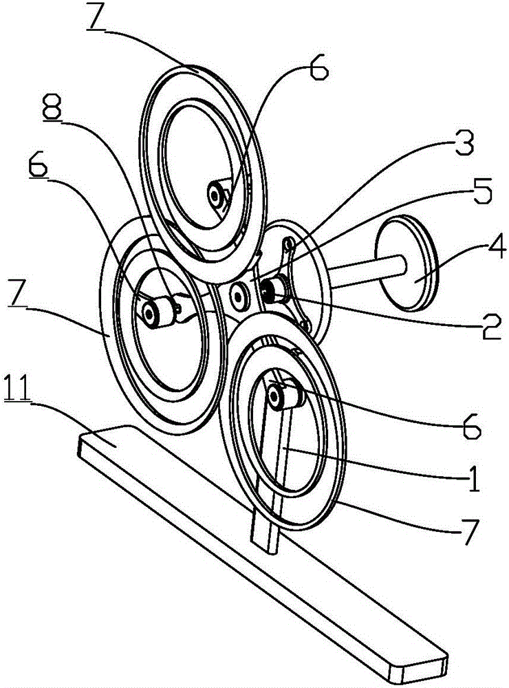
[0033] Such as figure 1 As shown, the experimental device for chaos phenomenon based on the pendulum ring includes a bracket 1, a main rotating shaft 2, and a three-jaw turntable 5 fixed on the main rotating shaft 2 and rotating synchronously with the main rotating shaft 2. The main rotating shaft 2 passes through the bearing seat 3 is installed on the support 1, and the side of the three-claw turntable 5 is fixed with three auxiliary rotating shafts 8 that are far away from the main rotating shaft 2 and arranged parallel to the main rotating shaft 2, and the auxiliary rotating shafts 8 are respectively fixed on The front ends of each claw of the three-claw turntable 5, the three claws of the three-claw turntable 5 are evenly distributed on the periphery of the main rotating shaft 2 at 120°, and the auxiliary rotating shaft 8 is equipped with a Rotating pendulum ring 7 , the axis of the auxiliary rotating shaft 8 is located in the ring of the pendulum ring 7 , the axis of the ...

Embodiment 2

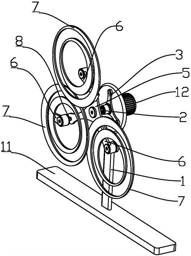
[0038] Such as figure 2 As shown, the difference from Embodiment 1 is that the end of the main rotating shaft 2 in the pendulum-ring-based chaos experiment device is provided with a motor 12 that drives the main rotating shaft 2 to rotate.

[0039] A detailed description of the working process of the demonstration device: first, the visitor or learner starts the motor 12 momentarily and then cuts off the power, and drives the demonstration device clockwise or counterclockwise to start demonstration. The three-jaw turntable 5 starts to rotate synchronously with the main rotating shaft 2; at this time, the eccentric piece 6 also starts its own free rotation around the auxiliary rotating shaft 8, and the direction and speed of rotation are uncertain; meanwhile, the pendulum The ring 7 is also started to rotate about the auxiliary rotation axis 8 via the eccentric 6 . During the rotation of the three pendulum rings 7, due to the difference in the initial force received, after a ...

Embodiment 3

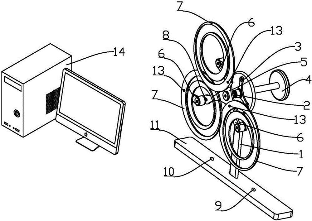
[0041] Such as image 3 As shown, the difference from Embodiment 1 is that the demonstration device also includes an infrared sensor 13 installed on the outer ring, a camera for capturing the signal of the infrared sensor, collecting the signal captured by the camera and The signal processing generates the computer 14 of the movement trajectory and the display for synchronous real-time display of said movement trajectory. The bracket 1 is fixedly mounted on a base 11, and a position sensor 9 and an electromagnetic driver 10 for driving the pendulum ring to continuously move are installed in the base 11.

[0042] A detailed description of the working process of the demonstration device: a detailed description of the working process of the above-mentioned demonstration device: first, the visitor or learner turns the rotary handle 4 clockwise or counterclockwise to drive the demonstration device to start the demonstration. The three-jaw turntable 5 starts to rotate synchronously...


PUM


Abstract

The invention relates to a chaos phenomenon experimental device based on a pendulum ring. The device comprises a bracket, a main rotating shaft and a turntable, wherein the turntable is fixed on the main rotating shaft and is capable of synchronously rotating following the main rotating shaft; the main rotating shaft is arranged on the bracket through a bearing base; an auxiliary rotating shaft which is away from the main rotating shaft and is parallel to the main rotating shaft is fixed on a side wall of the turntable; the pendulum ring capable of freely rotating around the auxiliary rotating shaft is arranged on the auxiliary rotating shaft; the axis of the auxiliary rotating shaft is located in the pendulum ring and is away from the center of the pendulum ring. A novel chaotic pendulum mechanism is designed by the invention. When the main rotating shaft is rotated, the pendulum ring can irregularly swing in a chaotic way around the rotating direction of the auxiliary rotating shaft. A visitor or leaner can clearly view the chaos phenomenon shown by the chaotic pendulum mechanism, so that the direct recognition of the visitor or leaner for the chaos phenomenon can be greatly promoted.

Description

technical field [0001] The invention belongs to the field of popular science education or teaching, and in particular relates to a chaotic phenomenon experimental device based on a pendulum ring. Background technique [0002] The certainty of a dynamical system is a mathematical concept, which means that the state of the system at any moment is determined by the initial state. Although the motion state at any future moment can be calculated according to the initial state data and motion laws of the motion, since the measurement of the initial state data cannot be completely accurate, errors in the predicted results are bound to occur, and even unpredictable. The predictability of motion is a physical concept. It is not contradictory that a movement can be unpredictable even if it is deterministic. The success of Newtonian mechanics, especially its success in predicting Neptune, has to a certain extent caused misunderstandings, equating certainty and predictability, thinkin...

Claims


Application Information

Patent Timeline
IPC IPC(8): G09B23/08G09B23/10
CPCG09B23/08G09B23/10
Inventor 李小瓯盛业涛李璇刘卫庄苏本林吉胜旺李瑞敏仝文浩洪先亮方猛
Owner HEFEI GENERAL MACHINERY RES INST
Why Eureka
Try Eureka