Contactor with low eddy-current loss

A technology of eddy current loss and contactor, which is applied in the field of electric power, can solve the problems of reducing the service life of contactors, noise, vibration, etc., and achieve the effects of reducing noise, reducing eddy current loss, and reducing eddy current loss

Inactive Publication Date: 2016-12-14
SICHUAN XINGZHI ZHIHUI INTPROP OPERATION CO LTD
View PDF5 Cites 2 Cited by
  • Summary
  • Abstract
  • Description
  • Claims
  • Application Information

AI Technical Summary

Problems solved by technology

When the magnetic flux passes through zero, the suction force it produces is also zero, and the moving iron core (armature) tends to leave, but before leaving, the magnetic flux rises quickly, and the moving iron core is sucked back, resulting in vibration and noise , reduce the service life of the contactor, and generate eddy current loss

Method used


Image

  • Contactor with low eddy-current loss
  • Contactor with low eddy-current loss

Examples


Embodiment 1

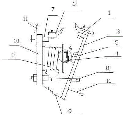
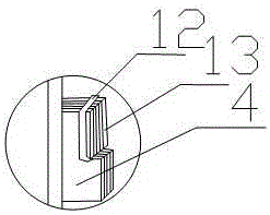
[0019] like Figure 1-2 As shown, the present invention includes a moving contact 1, an inductance coil 2, a rotating rod 3, an iron core 4, a static contact 6, a mounting base 7, a horizontal bar 8 and a base plate 10, the inductance coil 2, the mounting base 7, and The horizontal bar 8 is installed vertically on the bottom plate 10, the inductance coil 2 is located between the mounting seat 7 and the horizontal bar 8, and the iron core 4 is installed on the end face of the inductance coil 2, and the iron core 4 is formed by stacking and riveting a plurality of silicon steel sheets 13. The magnetic ring 12 is installed on the end face of the iron core 4, the static contact 6 is installed on the installation base 7; An armature 5 is also installed on the surface of the armature, and the armature 5 is opposite to the iron core 4, and a terminal 11 is arranged under the rotating rod 3 and on the mounting seat 7; the moving contact 1 is opposite to the static contact 6.

[0020]...

Embodiment 2

[0023] The preferred specific structure of this embodiment is as follows on the basis of Embodiment 1: the iron core 4 is divided into two layers, the two layers are staggered, each layer is riveted together by a plurality of silicon steel sheets 13 vertically stacked, only the top layer is equipped with magnetic ring 12. The two layers are staggered, the magnetic flux of the upper layer and the magnetic flux of the lower layer can work independently without affecting each other, and the upper layer of the core can better realize the magnetic flux passing through the narrow section of the sheet, and the eddy current is limited to some of the sheets. Narrow loops flow through, and the net electromotive force in these loops is small, the length of the loop is large, and because of the high resistivity of this thin sheet material, the eddy current loss can be significantly reduced.

Embodiment 3

[0025] This embodiment adds the following technical features on the basis of the above embodiments: a reaction spring 9 is connected between the bottom of the rotating rod 3 and the bottom of the bottom plate 10 . When the inductance coil is powered off, the iron core and the armature are separated. Due to the pull of the spring, the 360° rotation of the rotating rod is avoided, causing safety accidents, and damaging the moving contact on the rotating rod and the movable connection between the rotating rod and the horizontal bar. , improve the service life. When the iron core and the armature need to be pulled in, the reaction spring can be compressed without affecting the pull-in, which is flexible and convenient to use.

[0026] The opposite ends of the moving contact 1 and the static contact 6 are arc-shaped.

[0027] The angle range that the rotating rod 3 can rotate counterclockwise around the movable connection point on the horizontal bar 8 is 0-45°. While ensuring the...


PUM


Abstract

The invention discloses a contactor with low eddy-current loss. The contactor comprises a moveable contact, an inductance coil, a rotating rod, an iron core, a static contact, a mounting base, a horizontal cross bar and a base plate, wherein the inductance coil, the mounting base and the horizontal cross bar are vertically arranged on the base plate; the inductance coil is located between the mounting base and the horizontal cross bar; the iron core is arranged on an end face of the inductance coil; the iron core is formed by piling and pivoting a plurality of silicon steel sheets; a shading coil is arranged on the end face of the iron core; the static contact is arranged on the mounting base; the moveable contact is fixedly arranged at one end of the rotating rod; the horizontal cross bar is moveably connected with the other end of the rotating rod; an armature is also arranged on the surface of the rotating rod; the armature is opposite to the iron core; wiring terminals are arranged under the rotating rod and on the mounting base; the moveable contact is opposite to the static contact. The contactor with low eddy-current loss has a simple structure; through the specially arranged iron core, the shading coil is utilized to cause the iron core pass through two fluxes at different time, so that the total flux does not exceed zero; the noise is reduced; the eddy-current loss is reduced; the service life is prolonged.

Description

technical field [0001] The invention relates to the field of electric power, in particular to a contactor with low eddy current loss. Background technique [0002] The contactor is mainly used to control the direct circuit, and only transfers the power supply. The size of the electrical appliance is related to the rated current of the electrical appliance. In the current contactor, when the alternating current passes through the coil, the magnetic flux generated in the iron core changes with the same frequency as the current. When the current frequency is 50Hz, the magnetic flux passes through the zero point 100 times per second. When the magnetic flux passes through zero, the suction force it produces is also zero, and the moving iron core (armature) tends to leave, but before leaving, the magnetic flux rises quickly, and the moving iron core is sucked back, resulting in vibration and noise , reduce the service life of the contactor, and generate eddy current loss. The ed...

Claims


Application Information

Patent Timeline
Patent Type & Authority Applications(China)
IPC IPC(8): H01H50/36
CPCH01H50/36
Inventor 贺昶明
Owner SICHUAN XINGZHI ZHIHUI INTPROP OPERATION CO LTD
Why Eureka
Try Eureka