
Cable protection tube mouth sealing sleeve

A technology of cable protection tubes and envelopes, which is applied in the direction of cable inlet sealing devices and electrical components, which can solve problems such as endangering the safe operation of the power grid, accumulating heavy rainwater, and declining cable insulation levels, so as to reduce operation and maintenance costs and improve work efficiency , the effect of reducing the number of power outages

Inactive Publication Date: 2016-12-14
赵亮
View PDF6 Cites 3 Cited by
  • Summary
  • Abstract
  • Description
  • Claims
  • Application Information

AI Technical Summary

Problems solved by technology

In the past, organic fireproof blockage and concrete were mainly used for sealing. The conventional sealing method has poor moisture-proof and moisture-proof effects, and is not beautiful. After a period of use, cracks and water seepage will appear, and some will fall off as a whole, causing no blocking effect
Especially in the rainy summer season, the humidity in the cable protection tube is very high, and even a large amount of rainwater will accumulate. When the cable is operated in an environment with high humidity and rainwater for a long time, the insulation layer of the cable will be severely corroded, and the insulation level of the cable will be seriously damaged. It is easy to cause phase-to-phase and phase-to-ground short-circuit discharge, which affects the safe operation of the power system
At the same time, the cable protection tube will also be corroded in the environment of rainwater immersion or high humidity, and then it will be damaged and destroyed, which will not provide the proper protection and seriously endanger the safe operation of the power grid.

Method used


Image

  • Cable protection tube mouth sealing sleeve
  • Cable protection tube mouth sealing sleeve
  • Cable protection tube mouth sealing sleeve

Examples


Embodiment Construction

[0017] The present invention will be further elaborated below in conjunction with the accompanying drawings and specific embodiments.

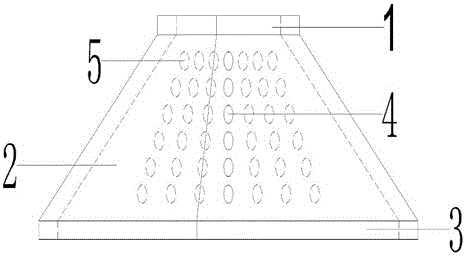
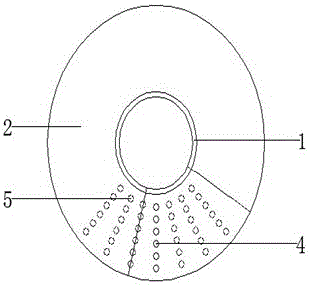
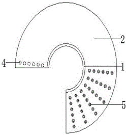
[0018] Such as Figure 1-6 As shown, a cable protection pipe mouth cover includes an upper seal 1, a cover main body 2, a lower seal 3, a buckle 4 and a concealed socket 5, the upper part of the cover main body 2 is provided with an upper seal 1, and the cover main body 2 is provided with a lower seal 3, and the upper seal 1, the envelope body 2 and the lower seal 3 are integrally casted, and a row of buckles 4 is provided on the edge of one end of the envelope body 2, and a plurality of columns are arranged at the other end Concealed sockets 5, and buckles 4 and concealed sockets 5 are evenly arranged on the surface of the main body of the envelope. According to cables 6 of different diameters, the sockets 4 are installed and fixed together with one row of concealed sockets 5.

[0019] The nozzle cover of the cable protection pipe of the pre...


PUM


Abstract

The invention discloses a cable protection tube mouth sealing sleeve. The cable protection tube mouth sealing sleeve comprises an upper sealing port, a sealing sleeve body, a lower sealing port, insertion buckles and hidden insertion holes, wherein the upper sealing port is formed in the upper portion of the sealing sleeve body, the lower sealing port is formed in the lower portion of the sealing sleeve body, and the upper sealing port, the sealing sleeve body and the lower sealing port are integrally formed through casting; a row of insertion buckles are arranged on the edge of one end of the sealing sleeve body, multiple rows of hidden insertion holes are formed in the other end of the sealing sleeve body, the insertion buckles and the hidden insertion holes are evenly arranged on the surface of the sealing sleeve body, and the insertion buckles and one row of hidden insertion holes are fixedly installed together according to the diameter of a cable. A cable and a cable protection tube can be protected for a long term, safety of people and equipment is ensured, working efficiency is improved, outage frequency and operation maintenance expenses are reduced, and blocking of a cable protection tube mouth is effectively avoided.

Description

technical field [0001] The invention relates to the field of electric appliances, in particular to a cable protection pipe opening cover. Background technique [0002] In recent years, with the continuous improvement of urban planning and power construction requirements and the needs of power construction, it is often necessary to bury cables in power transmission and distribution lines. In order to protect the cables from damage, it is necessary to install cable protection tubes underground and at a certain distance above the ground. In order to prevent rainwater from entering the pipe or other objects from entering the pipe when it rains, the upper opening of the protective pipe above the ground needs to be blocked. In the past, organic fireproof blockage and concrete were mainly used for sealing. The conventional sealing method has poor moisture-proof and moisture-proof effects, and is not beautiful. After a period of use, cracks and water seepage will appear, and some w...

Claims


Application Information

Patent Timeline
Patent Type & Authority Applications(China)
IPC IPC(8): H02G3/04H02G15/013
CPCH02G3/0406H02G3/0418H02G15/013
Inventor 赵亮
Owner 赵亮
Learn More