
A motor automatic assembly line

An automatic assembly and production line technology, applied in the direction of electric components, electromechanical devices, manufacturing motor generators, etc., can solve the problems of reducing installation accuracy, installation errors, and increasing labor costs, so as to prevent damage to components, avoid bumps and damage, The effect of reducing labor intensity

Active Publication Date: 2018-06-15
HUZHOU YUEQIU MOTOR
View PDF6 Cites 0 Cited by
  • Summary
  • Abstract
  • Description
  • Claims
  • Application Information

AI Technical Summary

Problems solved by technology

At present, the commonly used installation method is to install by division, that is, to use multiple devices to install the corresponding parts, which requires corresponding operators to operate, which increases the labor cost. Assembling a motor requires multiple circulations, each circulation It will consume corresponding time, which not only affects the assembly efficiency of the motor, but also increases the labor intensity of workers; moreover, it is easy to cause bumps or damage to the completed assembled parts during the circulation process, and at the same time, because the interior of the newly assembled parts is not yet It is very stable, and the transfer will affect the internal connection structure of the newly assembled parts and affect its assembly quality; in addition, each time the corresponding parts are installed, they need to be repositioned, so each installation will produce a corresponding installation error. After multiple installations, the installation error will expand, reducing the installation accuracy, thus affecting the quality of the installation
Therefore, the existing assembly has the characteristics of low assembly efficiency, high assembly cost, high labor intensity, large assembly error and unsatisfactory assembly quality.

Method used


Image

  • A motor automatic assembly line
  • A motor automatic assembly line
  • A motor automatic assembly line

Examples


Embodiment Construction

[0022] The present invention will be further described below in conjunction with the accompanying drawings and examples, but not as a basis for limiting the present invention.

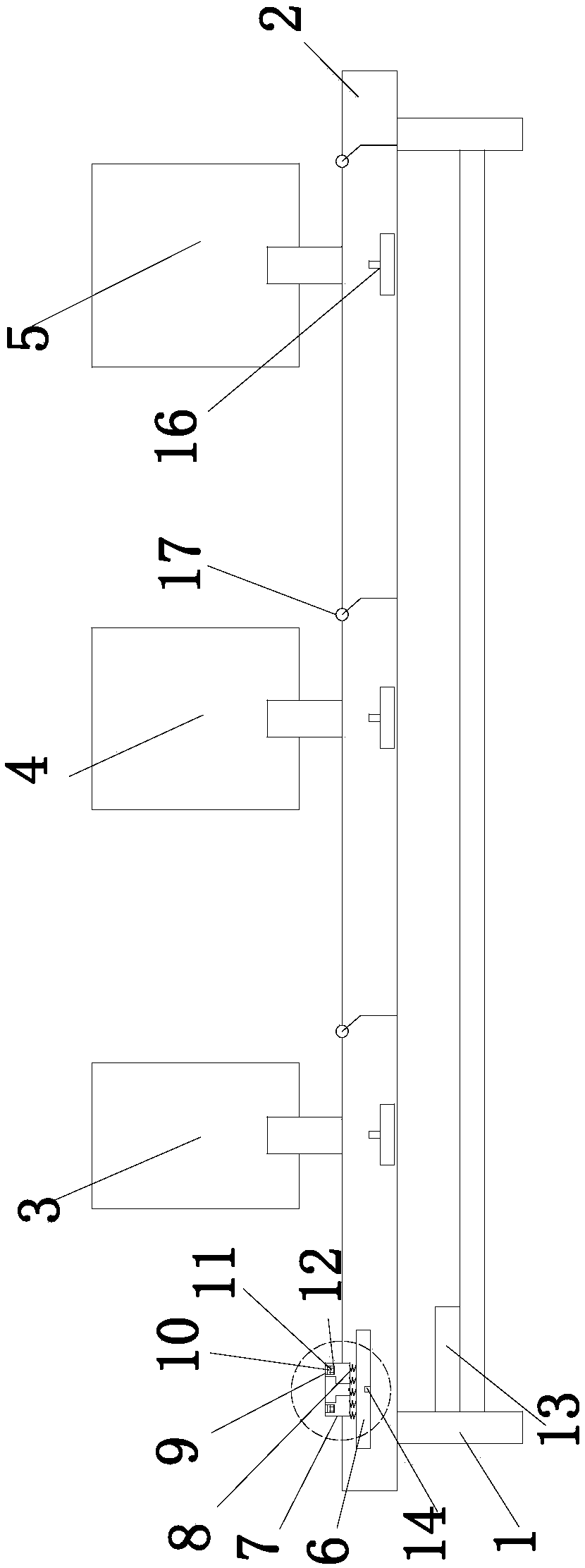
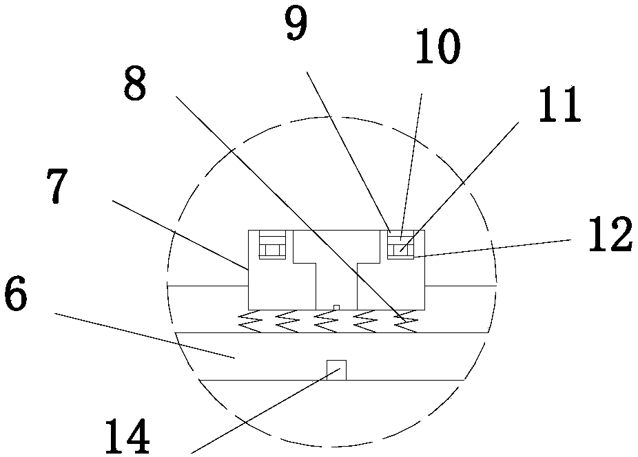
[0023] Example. An automatic motor assembly production line, consisting of Figure 1 to Figure 10 As shown, a frame 1 is included, and a conveyor chain 2 is provided on the frame 1, and a stator installation device 3 fixed to the frame 1, a rotor installation device 4 and an end cover installation device 5 are sequentially provided above the conveyor chain 2; The conveyor chain 2 is provided with a group of fixed bases 6, the fixed base 6 is provided with a casing fixed mold 7 corresponding to the shape of the casing, and a buffer spring 8 is arranged between the casing fixed mold 7 and the fixed base 6, The upper end surface of the fixed mold 7 of the casing is provided with a plurality of circular arc grooves 9, and a fixed ring 10 of an arc structure is arranged in the circular arc groove 9, and a ...


PUM


Abstract

The invention discloses an automatic motor assembly production line, comprising a frame (1), wherein a conveying chain (2) is arranged on the frame (1), and a stator installation device (3), a rotator installation device (4) and an end cover installation device (5) are arranged above the conveying chain (2) in sequence; a fixed base (6) is arranged above the conveying chain (2), an enclosure fixing mold (7) is arranged on the fixed base (6) and provided with an annular arc groove (9), a fixed ring (10) is arranged in the annular arc groove (9), a group of hydraulic rod (11) is arranged between the fixed ring (10) and the annular arc groove (9), the end of the hydraulic rod (11) is connected with a rotating assembly (12), and both the rotating assembly (12) and the hydraulic rod (11) are connected with a controller (13). The automatic motor assembly production line has the advantages of high assembly efficiency, low assembly cost, low worker labor intensity, small assembly error and good assembly quality.

Description

technical field [0001] The invention relates to a motor assembly equipment, in particular to a motor automatic assembly production line. Background technique [0002] The motor is composed of parts such as the motor housing, stator, rotor and end cover, so after the parts are manufactured, they need to be assembled together. At present, the commonly used installation method is to install by division, that is, to use multiple devices to install the corresponding parts, which requires corresponding operators to operate, which increases the labor cost. Assembling a motor requires multiple circulations, each circulation It will consume corresponding time, which not only affects the assembly efficiency of the motor, but also increases the labor intensity of workers; moreover, it is easy to cause bumps or damage to the completed assembled parts during the circulation process, and at the same time, because the interior of the newly assembled parts is not yet It is very stable, and...

Claims


Application Information

Patent Timeline
Patent Type & Authority Patents(China)
IPC IPC(8): H02K15/00
CPCH02K15/0006H02K15/005
Inventor 朱国良张建军钟大志史国强沈建强
Owner HUZHOU YUEQIU MOTOR
Learn More