Method for determining error of an inertial sensor

An inertial sensor and sensor technology, applied in the direction of brakes, brake action activation devices, vehicle components, etc., can solve the problem of not being able to ensure sufficient compensation errors, and achieve the effect of improving accuracy

Active Publication Date: 2020-02-07
CONTINENTAL AUTOMOTIVE TECH GMBH
View PDF9 Cites 0 Cited by
  • Summary
  • Abstract
  • Description
  • Claims
  • Application Information

AI Technical Summary

Problems solved by technology

Therefore it is not possible to ensure adequate compensation for the errors currently present

Method used


Image

  • Method for determining error of an inertial sensor
  • Method for determining error of an inertial sensor
  • Method for determining error of an inertial sensor

Examples


Embodiment Construction

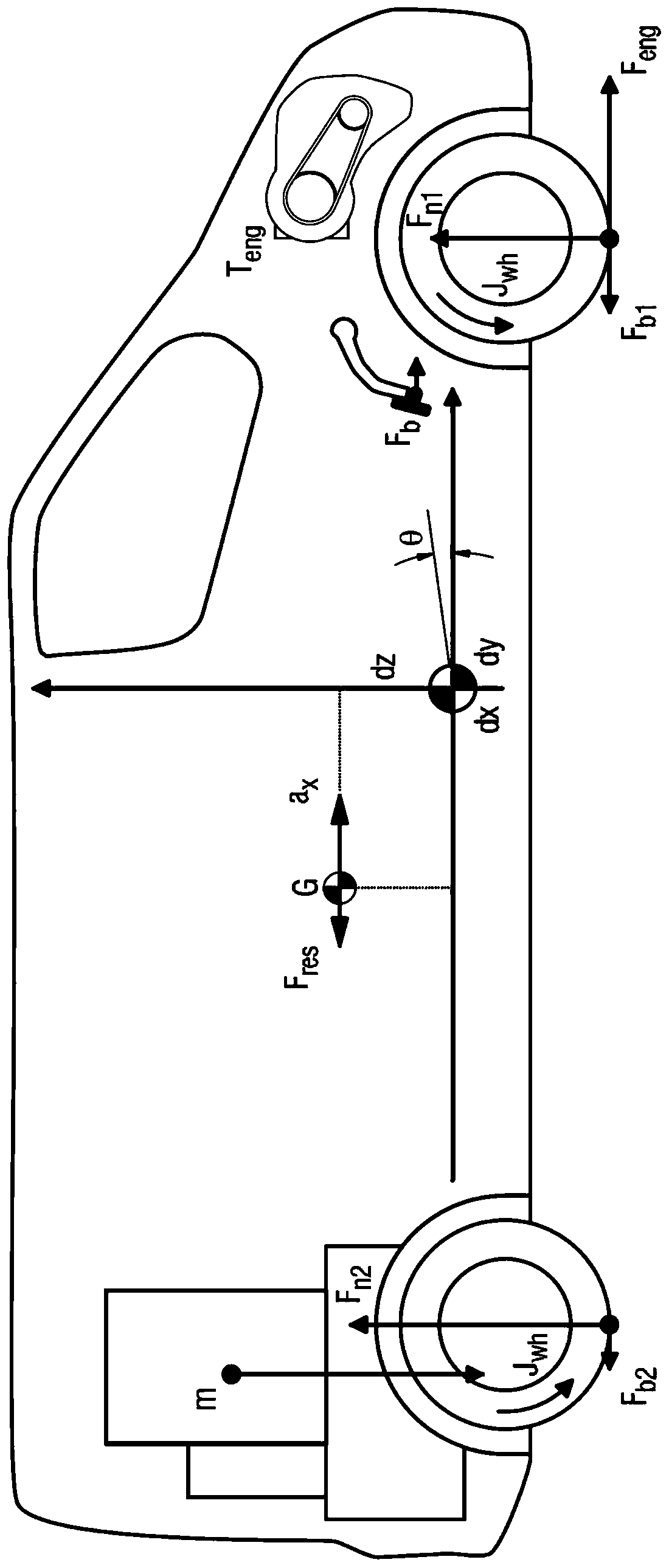
[0038] figure 1 A side view of an exemplary vehicle is shown schematically illustrating the effects of forces and asymmetric loads.

[0039] The engine torque T of the drive engine, such as an internal combustion engine eng In this example the driving force F is transmitted through the wheels of the front axle and causes the vehicle eng . Moment of inertia J of the wheel wh Indicates that a portion of the power applied by the drive engine is also converted into rotational energy of the wheels and drive train. If the acting braking forces or running resistances such as rolling resistance and air resistance are considered, then the longitudinal velocity v of the vehicle is caused x increase acceleration force F acc It can be calculated from the difference between driving force and braking force:

[0040]

[0041] For simplicity, it is assumed that the vehicle is driven on a flat route and the vehicle mass m is known Fzg .

[0042] If the driver applies a certain for...


PUM


Abstract

The invention relates to a method for determining an additional deviation of a longitudinal acceleration signal of a moving motor vehicle measured by an inertial sensor, at least detecting the longitudinal acceleration signal, a braking signal and a drive signal, and analyzing the forces of the longitudinal dynamics of the motor vehicle balance. The signals are detected both during at least one acceleration process and at least one braking process. The signal during acceleration is detected and / or analyzed separately from the signal during braking, and the additional deviation is obtained by combining the signal detected during acceleration or the value calculated therefrom with the signal detected during braking or The values ​​thus calculated are compared and determined. The invention also relates to an electronic controller.

Description

technical field [0001] The invention relates to a method for determining an additional deviation of a longitudinal acceleration signal of a moving motor vehicle measured by an inertial sensor and to an electronic control device. Background technique [0002] The driving performance of motor vehicles, particularly vehicles used commercially to transport goods, can be significantly affected by load conditions. Various methods are therefore already known for estimating the vehicle mass, which only use the signals of sensors provided for driving dynamics control. If the longitudinal dynamics of the vehicle during the acceleration process are considered, the force balance can be analyzed and the vehicle mass can be calculated as the quotient of the difference between the driving and braking forces as the denominator and the resulting acceleration as the numerator. [0003] In order to take into account the influence of the gradient during the estimation of the vehicle mass, it i...

Claims


Application Information

Patent Timeline
Patent Type & Authority Patents(China)
IPC IPC(8): B60W40/105B60W40/107B60T8/1755B60W40/13
CPCB60T8/17551B60W40/105B60W40/107B60W40/13B60W2510/0657B60W2510/083B60W2510/182B60W2520/10B60T2250/02B60T2250/06B60T13/06B60T2250/03B60Y2400/304B60Y2400/306B60T7/042
Inventor C·张J·莱夫里尔
Owner CONTINENTAL AUTOMOTIVE TECH GMBH
Why Eureka
Try Eureka