Filter device for laboratory

A filtration device and laboratory technology, applied in filtration and separation, fixed filter element filters, chemical instruments and methods, etc., can solve the problems of slow filtration, low efficiency, time-consuming filtration, etc., to speed up the filtration rate , the effect of improving experimental efficiency

Pending Publication Date: 2016-12-21
成都铭利特生物科技有限公司
View PDF0 Cites 1 Cited by
  • Summary
  • Abstract
  • Description
  • Claims
  • Application Information

AI Technical Summary

Problems solved by technology

[0002] The filter in the laboratory is usually mainly the gravity of the liquid or the osmotic pressure difference or the vacuum method to separate the product precipitated in the solution. Special vacuum equipment, and the products of these three filtration methods will stick to the wall of the filter tank later, making the filtration speed slower. Chemical experiments, especially organic experiments, can range from hours to days at most. The efficiency is relatively low, and one of the important reasons is that filtration takes time. Therefore, it is necessary to find a filtration device that can increase the filtration rate and thus improve the experimental efficiency.

Method used


Image

  • Filter device for laboratory
  • Filter device for laboratory

Examples


Embodiment 1

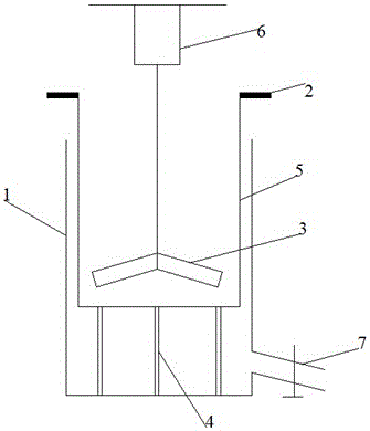
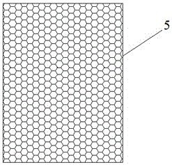
[0017] In this example, if figure 1 with figure 2 As shown, a filter device for laboratory use includes a filter tank 5 with an open top, and the side and bottom surfaces of the filter tank 5 are evenly provided with filter holes, and the top of the filter tank 5 opening is provided with a shaft vertically The lower motor 6 is connected to the agitator 3 with a rotating shaft, and the stirring paddle of the agitator 3 is in the filter tank 5 .

[0018] The working process of the present invention is: earlier the bottom of filter pool 5 is wetted, and filter paper is placed on the bottom of filter pool 5 and fully covers the bottom of filter pool 5, and is placed a container for containing filtrate directly below filter pool 5. Containers, solutions often have corrosiveness, according to the difference of the solution, use containers of different materials to hold the filtered solution, then pour the fully reacted solution into the filter pool 5, start the motor 6, in order t...

Embodiment 2

[0020] In this embodiment, a liquid holding pool 1 is further added on the basis of the above-described embodiments. The outside of the filter pool 5 is provided with a liquid holding pool 1 for adorning filtrate. In the present invention, adding a liquid holding pool 1 can eliminate the need to The liquid holding pool 1 is placed separately, which reduces labor and saves time. Other parts of this embodiment are the same as those of Embodiment 1, and will not be repeated here.

Embodiment 3

[0022] In this embodiment, a support column 4 is further added on the basis of the above-mentioned embodiment. A support column 4 for supporting the filter tank 5 is provided between the bottom of the filter tank 5 and the bottom of the liquid holding tank 1. The function of the support column 4 is It is not to allow the filter tank 5 to be soaked in the solution of the liquid holding tank 1, which will cause difficulty in filtration. If there is no supporting column 4 after the filtration is completed, there will be negative pressure between the filter tank 5 and the liquid holding tank 1, which is difficult to separate. Other parts of this embodiment are the same as those of the foregoing embodiment, and will not be repeated here.


PUM


Abstract

The invention discloses a filter device for a laboratory and belongs to the field of laboratory filter devices. The filter device solves the problems that in the prior art, a filter device of a laboratory is low in filter speed or external equipment such as vacuum pumping equipment needs to be used in the filtering process, cost is high, and much land is occupied. The filter device comprises a filter tank with a top opening, filtering holes are evenly formed in the side faces and the bottom face of the filter tank, a motor with a vertically-downward rotating shaft is arranged above the opening of the filter tank, the rotating shaft is connected with a stirrer, and stirring paddles of the stirrer are arranged in the filter tank. According to the filter device, by arranging the stirrer to improve the disturbing degree of a solution to be filtered in the filtering process, solid matter is prevented from adhering to the wall of the filter tank, the filtering speed is increased, and experiment efficiency is improved.

Description

technical field [0001] The invention relates to the field of laboratory filtering devices, in particular to a laboratory filtering device. Background technique [0002] The filter in the laboratory is usually mainly the gravity of the liquid or the osmotic pressure difference or the vacuum method to separate the product precipitated in the solution. Special vacuum equipment, and the products of these three filtration methods will stick to the wall of the filter tank later, making the filtration speed slower. Chemical experiments, especially organic experiments, can range from hours to days at most. The efficiency is relatively low, and one of the important reasons is that filtration takes time. Therefore, it is very necessary to find a filtration device that can increase the filtration rate and thus improve the experimental efficiency. Contents of the invention [0003] The object of the present invention is to provide a laboratory filter device which improves the filtrat...

Claims


Application Information

Patent Timeline
IPC IPC(8): B01D29/075
CPCB01D29/05B01D29/075
Inventor 杨素贤
Owner 成都铭利特生物科技有限公司
Why Eureka
Try Eureka