Reaction device and reaction equipment

A reaction device and reaction equipment technology, applied in chemical/physical processes, chemical instruments and methods, etc., can solve problems such as inability to meet heat exchange requirements, catalyst wear, and small heat exchange area, so as to improve reaction activity and reaction selectivity , increase the heat exchange area, and solve the effect of heat transfer problems

Inactive Publication Date: 2016-12-21
CHENGDU SEPMEM SCI & TECH
View PDF8 Cites 5 Cited by
  • Summary
  • Abstract
  • Description
  • Claims
  • Application Information

AI Technical Summary

Problems solved by technology

Traditional catalytic bed reactors, such as fixed bed reactors and fluidized bed reactors, have shown their limitations in many engineering applications due to their respective shortcomings in material transfer and heat transfer
For example, fixed bed reactors have problems such as uneven bed temperature distribution, hot spots / cold spots, and small heat transfer area per unit volume, which cannot meet the heat transfer requirements of some strong exothermic / endothermic reactions; fluidized bed reactions There are problems such as large material backmixing and serious catalyst wear

Method used


Image

  • Reaction device and reaction equipment
  • Reaction device and reaction equipment
  • Reaction device and reaction equipment

Examples


Embodiment 1

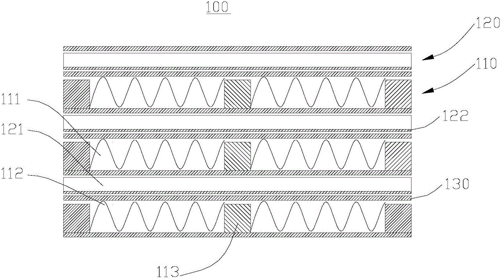
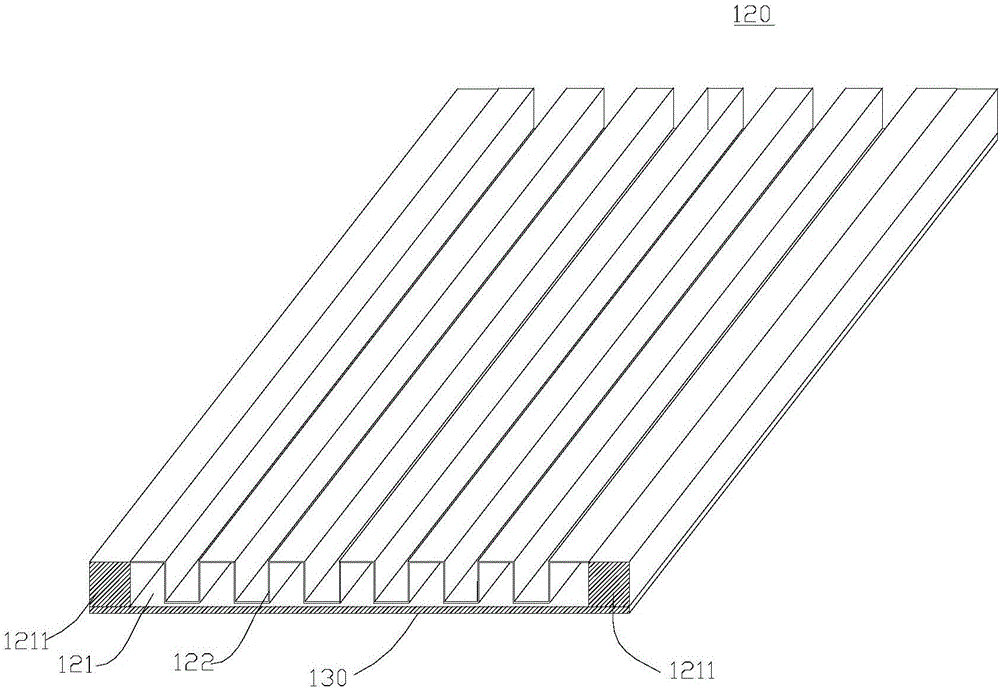
[0039] Please refer to figure 1 , this embodiment provides a reaction device 100 , including a reaction unit 110 and a heat exchange unit 120 , and the reaction unit 110 and the heat exchange unit 120 are connected through a heat exchange plate 130 . The reaction unit 110 includes a first channel 111 , a first fin 112 , and a support bar 113 ; the heat exchange unit 120 includes a second channel 121 and a second fin 122 .

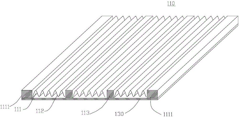
[0040] refer to figure 2 , the reaction unit 110 is a hollow cuboid. The reaction unit 110 has a first channel 111 extending therethrough. In this embodiment, the reaction unit 110 includes two first sealing strips 1111 arranged in parallel and a heat exchange plate 130 . Further, the two first sealing strips 1111 are arranged parallel to the edge of the heat exchange plate 130 and perpendicular to the heat exchange plate 130 . The two first sealing strips 1111 are surrounded by the heat exchange plate 130 to form a U-shaped structure. Wherein, the th...

Embodiment 2

[0052] Please refer to Figure 4 , this embodiment provides a reaction device 200 , which includes the reaction device 100 in Embodiment 1, and further includes a housing 210 , a reactant inlet 220 , a reactant outlet 230 , a heat exchange inlet 240 and a heat exchange outlet 250 .

[0053] refer to Figure 4 and Figure 5 , the casing 210 is a hollow cuboid. A first end cover 3101 and a second end cover 3102 are detachably disposed on opposite sides of the housing 210 . Further, the first end cover 3101 is a spherical arc structure, and the first end cover 3101 is detachably connected to one end of the housing 210 through the first flange 3701; the second end cover 3102 is a spherical arc structure, and the second end The cover 3102 is detachably connected to the other end of the housing 210 through the second flange 3702 .

[0054] The reactant inlet 220 is disposed on the first end cap 3101 . The reactant outlet 230 is disposed on the second end cap 3102 . The reactan...

Embodiment 3

[0069] Please refer to Figure 7 , this embodiment provides a reaction device 200 , which is substantially the same as the second embodiment, the difference between the two is that the reaction device 100 of this embodiment further includes a third channel 330 .

[0070] The shell 210 is a hollow cylinder, and the reaction device 100 is arranged inside. The reaction device 100 is provided with a third passage 330, one end of the third passage 330 communicates with the reactant inlet 220, and the other end of the third passage 330 is away from the first passage 111 through the gap between the housing 210 and the reaction device 100. One end of the material outlet 230 is connected.

[0071] In this embodiment, the reaction device 200 has only one third end cover 3103 , and the third end cover 3103 is connected to the casing 210 through a third flange 3703 . A fifth accommodating chamber 300 is disposed between the third channel 330 and the reactant inlet 220 . The reactant in...


PUM


Abstract

The invention relates to a reaction device. The reaction device comprises a plurality of reaction units and a plurality of heat exchange units, which are arranged in a staggered manner and are connected through heat exchange plates, wherein each reaction unit is provided with perforative first passages; each heat exchange unit is provided with perforative second passages; and first fins are arranged in each first passage, and second fins are arranged in each second passage. The reaction device has outstanding effects. Reaction equipment comprises the reaction device and also comprises a hollow airtight shell, a reactant inlet, a reactant outlet, a heat exchange inlet and a heat exchange outlet, wherein the reactant inlet, the reactant outlet, the heat exchange inlet and the heat exchange outlet are formed in the shell, and the reaction device is arranged in the shell. Two ends of each first passage respectively communicate with the reactant inlet and the reactant outlet, and two ends of each second passage respectively communicate with the heat exchange inlet and the heat exchange outlet. The reaction equipment is high in reaction efficiency.

Description

technical field [0001] The invention relates to the field of chemical industry, in particular to a reaction device and reaction equipment. Background technique [0002] Most of the gas-solid catalytic reactions in the chemical industry are strongly exothermic or endothermic, such as methanol synthesis, carbon monoxide shift, synthesis gas to methane, ammonia synthesis, methanol to olefins, natural gas reforming to hydrogen, etc. The research and improvement of catalytic bed reactors in these strong exothermic or strong endothermic reactions has always been a research hotspot. Traditional catalytic bed reactors, such as fixed bed reactors and fluidized bed reactors, have shown their limitations in many engineering applications due to their respective shortcomings in mass transfer and heat transfer. For example, fixed bed reactors have problems such as uneven bed temperature distribution, hot spots / cold spots, and small heat transfer area per unit volume, which cannot meet th...

Claims


Application Information

Patent Timeline
Patent Type & Authority Applications(China)
IPC IPC(8): B01J8/04
CPCB01J8/04B01J8/0496B01J2208/00212
Inventor 张惊涛陈小林
Owner CHENGDU SEPMEM SCI & TECH
Why Eureka
Try Eureka